Toshiba Satellite L645-S4102 User Manual - Page 54
For this model, Slot A is the bottom slot. Slot B is the top slot. If only
 |
View all Toshiba Satellite L645-S4102 manuals
Add to My Manuals
Save this manual to your list of manuals |
Page 54 highlights
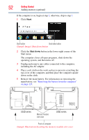
54 Getting Started Adding memory (optional) NOTE For this model, Slot A is the bottom slot. Slot B is the top slot. If only one memory module is to be installed, it must be installed in Slot A. 11 Pick up the memory module by its sides, avoiding any contact with its connector. Position the module toward the socket, aligning the connector's notch with the matching key in the socket. notch latch connector latch key (Sample Illustration) Aligning the memory module with the socket 12 Firmly press the memory module into the memory slot's socket at approximately a 30-degree angle (to the horizontal surface of the computer). (Sample Illustration) Inserting the memory module into the socket
-
 1
1 -
2
-
3
-
4
-
5
-
6
-
7
-
8
-
9
-
10
-
11
-
12
-
13
-
14
-
15
-
16
-
17
-
18
-
19
-
20
-
21
-
22
-
23
-
24
-
25
-
26
-
27
-
28
-
29
-
30
-
31
-
32
-
33
-
34
-
35
-
36
-
37
-
38
-
39
-
40
-
41
-
42
-
43
-
44
-
45
-
46
-
47
-
48
-
 49
49 -
 50
50 -
 51
51 -
 52
52 -
 53
53 -
 54
54 -
 55
55 -
 56
56 -
 57
57 -
 58
58 -
 59
59 -
60
-
61
-
62
-
63
-
64
-
65
-
66
-
67
-
68
-
69
-
70
-
71
-
72
-
73
-
74
-
75
-
76
-
77
-
78
-
79
-
80
-
81
-
82
-
83
-
84
-
85
-
86
-
87
-
88
-
89
-
90
-
91
-
92
-
93
-
94
-
95
-
96
-
97
-
98
-
99
-
100
-
101
-
102
-
103
-
104
-
105
-
106
-
107
-
108
-
109
-
110
-
111
-
112
-
113
-
114
-
115
-
116
-
117
-
118
-
119
-
120
-
121
-
122
-
123
-
124
-
125
-
126
-
127
-
128
-
129
-
130
-
131
-
132
-
133
-
134
-
135
-
136
-
137
-
138
-
139
-
140
-
141
-
142
-
143
-
144
-
145
-
146
-
147
-
148
-
149
-
150
-
151
-
152
-
153
-
154
-
155
-
156
-
157
-
158
-
159
-
160
-
161
-
162
-
163
-
164
-
165
-
166
-
167
-
168
-
169
-
170
-
171
-
172
-
173
-
174
-
175
-
176
-
177
-
178
-
179
-
180
-
181
-
182
-
183
-
184
-
185
-
186
-
187
-
188
-
189
-
190
-
191
-
192
-
193
-
194
-
195
-
196
-
197
-
198
-
199
-
200
-
201
-
202
-
203
-
204
-
205
-
206
-
207
-
208
-
209
-
210
-
211
-
212
-
213
-
214
-
215
-
216
-
217
-
218
-
219
-
220
-
221
-
222
-
223
-
224
-
225
-
226
-
227
-
228
-
229
 |
 |
54
Getting Started
Adding memory (optional)
For this model, Slot A is the bottom slot. Slot B is the top slot. If only
one memory module is to be installed, it must be installed in Slot A.
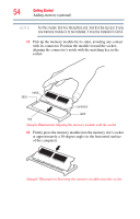
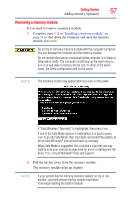
11
Pick up the memory module by its sides, avoiding any contact
with its connector. Position the module toward the socket,
aligning the connector’s notch with the matching key in the
socket.
(Sample Illustration) Aligning the memory module with the socket
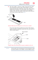
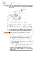
12
Firmly press the memory module into the memory slot’s socket
at approximately a 30-degree angle (to the horizontal surface
of the computer).
(Sample Illustration) Inserting the memory module into the socket
NOTE
latch
latch
key
notch
connector