Toshiba Satellite M30X Maintenance Manual
Toshiba Satellite M30X Manual
 |
View all Toshiba Satellite M30X manuals
Add to My Manuals
Save this manual to your list of manuals |
Toshiba Satellite M30X manual content summary:
- Toshiba Satellite M30X | Maintenance Manual - Page 1
Toshiba Personal Computer Satellite M30X Maintenance Manual TOSHIBA CORPORATION - Toshiba Satellite M30X | Maintenance Manual - Page 2
use of the information contained herein. Toshiba Personal Computer Satellite M30X Maintenance Manual First edition September 2004 Disclaimer The information presented in this manual has been reviewed and validated for accuracy. The included set of instructions and descriptions are accurate for the - Toshiba Satellite M30X | Maintenance Manual - Page 3
Preface This maintenance manual describes how to perform hardware service maintenance for the Toshiba Personal Computer Satellite SATELLITE M30X, referred to as the M30X Series in this manual. The procedures described in this manual are intended to help service technicians isolate faulty Field - Toshiba Satellite M30X | Maintenance Manual - Page 4
M30X Series system unit and each FRU. Chapter 2 Troubleshooting Procedures explains how to diagnose and resolve FRU problems. Chapter 3 Test and Diagnostics describes how to perform test and diagnostic operations for maintenance service list ‰ Reliability iv Satellite M30X Maintenance Manual - Toshiba Satellite M30X | Maintenance Manual - Page 5
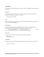
Conventions This manual uses the following formats to describe, identify, and highlight terms and hold down the first two and at the same time press the third. User input Text that you are instructed to type in is shown in the boldface type below: DISKCOPY A: B: The display Text generated by the - Toshiba Satellite M30X | Maintenance Manual - Page 6
vi Satellite M30X Maintenance Manual - Toshiba Satellite M30X | Maintenance Manual - Page 7
2-21 2.9 TouchPad Troubleshooting 2-23 2.10 Speaker Troubleshooting 2-25 2.11 Optical Drive Troubleshooting 2-27 2.12 Modem Troubleshooting 2-30 2.13 PCMCIA Troubleshooting 2-32 2.14 IEEE 1394 Troubleshooting 2-34 2.15 Wireless LAN Troubleshooting 2-36 Satellite M30X Maintenance Manual vii - Toshiba Satellite M30X | Maintenance Manual - Page 8
Test...3-8 3.6 IEEE 1394 Test ...3-9 3.7 Speaker Audio Test ...3-10 3.8 Fan ON/OFF Test...3-11 3.9 Main Battery Charge Test 3-12 3.10 FDD Test ...3-13 3.11 CD-ROM Test ...3-14 3.12 Keyboard Test ...3-15 3.18 RTC Test ...3-25 3.19 CD Control Button Test 3-26 viii Satellite M30X Maintenance Manual - Toshiba Satellite M30X | Maintenance Manual - Page 9
Chapter 4 Replacement Procedures 4.1 General...4-1 4.2 Battery...4-7 4.3 PC Card...4-9 4.4 HDD...4-11 4.5 Optical Drive Module ...4-13 4.6 Optical Drive...4-15 4.7 Wireless LAN 39 4.17 Display Mask ...4-42 4.18 LCD Module ...4-44 4.19 FL Inverter Board ...4-47 Satellite M30X Maintenance Manual ix - Toshiba Satellite M30X | Maintenance Manual - Page 10
Appendices Appendix A Handling the LCD Module A-1 Appendix B Board Layout...B-1 Appendix C Pin Assignments C-1 Appendix D Keyboard Scan/Character Codes D-1 Appendix E Key Layout ...E-1 Appendix F Series Screw Torque List F-1 Appendix G Reliability ...G-1 x Satellite M30X Maintenance Manual - Toshiba Satellite M30X | Maintenance Manual - Page 11
Chapter 1 Hardware Overview 1 - Toshiba Satellite M30X | Maintenance Manual - Page 12
1 Hardware Overview 1-ii Satellite M30X Series Maintenance Manual - Toshiba Satellite M30X | Maintenance Manual - Page 13
Chapter 1 Contents 1 Hardware Overview 1.1 Features ...1-1 1.2 System Unit...1-6 1.3 2.5-inch Hard Disk Drive 1-11 1.4 Optical Device Drives 1-12 1.5 Power Supply ...1-12 1.6 Batteries ...1-14 1.6.1 Main Battery 1-14 1.6.2 RTC battery 1-15 Satellite M30X Series Maintenance Manual 1-iii - Toshiba Satellite M30X | Maintenance Manual - Page 14
1 Hardware Overview 1-iv Satellite M30X Series Maintenance Manual - Toshiba Satellite M30X | Maintenance Manual - Page 15
CPU ‰ Chipset • Intel 855GME • Intel ICH4-M • ENE KB910 for Keyboard Controller, Battery management Unit, and RTC. • ENE CB1410 for Card Bus PCMCIA controller or CB714 for SODIMM socket in the bottom side (one screw), support Toshiba accessory SODIMM Satellite M30X Series Maintenance Manual 1-1 - Toshiba Satellite M30X | Maintenance Manual - Page 16
Keyboard An easy-to-use 87-key keyboard provides a numeric keypad overlay for fast numeric data entry or for cursor and page control. It supports software that uses a 101- or 102-key enhanced keyboard. Includes one Windows® key and one Application key. 1-2 Satellite M30X Series Maintenance Manual - Toshiba Satellite M30X | Maintenance Manual - Page 17
, OTPROM, FLASH ROM • Mask ROM memory card • MODEM/LAN card • Card bus card • PC Card 8.0 Compliant, supports 3V and 5V cards ‰ Multiple Digital Media Card • ENE CB1410 controller for PCMCIA only, or ENE CB714 controller for PCMCIA and 5 in one reader Satellite M30X Series Maintenance Manual 1-3 - Toshiba Satellite M30X | Maintenance Manual - Page 18
• PCI card bus • NO ZV-Port support • With dummy card for PCMCIA • 5 in 1 reader,BTO(Rubber cap ) (Support XD, SD, SM, MS, MS Pro and MMC) • No SD-IO support ‰ Universal Serial Bus (USB) The computer utility.(The default setting is Windows Media Player) 1-4 Satellite M30X Series Maintenance Manual - Toshiba Satellite M30X | Maintenance Manual - Page 19
1.1 Features 1 Hardware Overview Satellite M30X Series Maintenance Manual 1-5 - Toshiba Satellite M30X | Maintenance Manual - Page 20
Dedicated 2FP(local flat panel) interface • Single or dual channel LVDS panel support up to WXGA panel, resolution with frequency range from 25MHZ to 112MHZ per channel. ‰ SMsC LPC 47N217 Super I/O with LPC Interface • PC99a, PC2001 • ACPI 2.0 Compliant 1-6 Satellite M30X Series Maintenance Manual - Toshiba Satellite M30X | Maintenance Manual - Page 21
Serial Port • High Speed NS 16C550A Compatible UARTs with Send/Receive 16-Byte FIFO • Supports 230k and 460k Baud • Programmable Baud Rate Generator • Modem Control Circuitry • Infrared . − Dual Microphone Inputs. − High Quality Differential CD Input. Satellite M30X Series Maintenance Manual 1-7 - Toshiba Satellite M30X | Maintenance Manual - Page 22
Revision 1.1 • Compliant with PCI Mobile Design Guide Version 1.1 • Compliant with Advanced Configuration and Support SD Suspend/Resume Functionality • Support DMA Mode to Minimize CPU Overhead • Support High Speed with the SD Clock Frequency Up to 50Mhz 1-8 Satellite M30X Series Maintenance Manual - Toshiba Satellite M30X | Maintenance Manual - Page 23
PME# from D3, D2, D1 and D0 • Supports PCI PME# from D3Cold • Supports D3STATE# (CB1410 only) • Power Switch Interface • CB1420 supports serial 3 wire power switch interface. • CB1410 supports parallel 4 wire power switch interface. • Misc Control Logic Satellite M30X Series Maintenance Manual 1-9 - Toshiba Satellite M30X | Maintenance Manual - Page 24
1 Hardware Overview • - Supports serial EEPROM interface • - Supports socket activity LED • - Supports 5 GPIOs and GPE# • - Supports standard Zoomed Video Port • - Supports SPKROUT, CAUDIO and RIOUT# • - Supports PCI LOCK# 1.2 System Unit 1-10 Satellite M30X Series Maintenance Manual - Toshiba Satellite M30X | Maintenance Manual - Page 25
The internal HDD is a random access non-volatile storage device. It has a non-removable 2.5inch magnetic disk and mini-Winchester type magnetic heads. The computer supports a 40 / 60 / 80GB/100G HDD. Satellite M30X Series Maintenance Manual 1-11 - Toshiba Satellite M30X | Maintenance Manual - Page 26
following input signal status: • System power ON/OFF status • Direct CD power ON/OFF status 5. Beep and LED control Beep is caused by the low battery status. The EC controls the following two kinds of LED 1-12 Satellite M30X Series Maintenance Manual - Toshiba Satellite M30X | Maintenance Manual - Page 27
a new battery is installed, the EC communicates with the E2PROM in the battery to read information of the newly installed battery. 10. Battery capacity calculation The EC reads battery remaining and percentage capacity from the battery through SMBus. Satellite M30X Series Maintenance Manual 1-13 - Toshiba Satellite M30X | Maintenance Manual - Page 28
a full charge when the AC adaptor and battery are attached to the computer. The system charges the battery using quick charge or trickle charge. ‰ Quick Battery Charge When the AC adaptor is attached, ) Charging time 12 hours or longer About 4 hours 1-14 Satellite M30X Series Maintenance Manual - Toshiba Satellite M30X | Maintenance Manual - Page 29
time and data preservation period of the RTC battery. The RTC battery is charged by the adaptor or main battery, while the computer is powered on. Status Charging Time (power on) Data preservation period (full charge) Time About 48 hours 2 month Satellite M30X Series Maintenance Manual 1-15 - Toshiba Satellite M30X | Maintenance Manual - Page 30
1 Hardware Overview 1.6 Batteries 1-16 Satellite M30X Series Maintenance Manual - Toshiba Satellite M30X | Maintenance Manual - Page 31
Chapter 2 Troubleshooting Procedures 2 - Toshiba Satellite M30X | Maintenance Manual - Page 32
2 Troubleshooting Procedures 2-ii Satellite M30X Series Maintenance Manual - Toshiba Satellite M30X | Maintenance Manual - Page 33
TouchPad Troubleshooting 2-23 2.10 Speaker Troubleshooting 2-25 2.11 Optical Drive Troubleshooting 2-27 2.12 Modem Troubleshooting 2-30 2.13 PCMCIA Troubleshooting 2-32 2.14 IEEE 1394 Troubleshooting 2-34 2.16 Wireless LAN Troubleshooting 2-36 Satellite A70 Series Maintenance Manual 2-iii - Toshiba Satellite M30X | Maintenance Manual - Page 34
troubleshooting process 2-27 Modem troubleshooting process 2-30 PCMCIA troubleshooting process 2-32 IEEE 1394 troubleshooting process 2-34 Wireless LAN troubleshooting process 2-36 Tables Table 2-1 Battery LED ...2-8 Table 2-2 DC-IN LED ...2-9 2-iv Satellite M30X Series Maintenance Manual - Toshiba Satellite M30X | Maintenance Manual - Page 35
drive troubleshooting 8. Cleaning kit for optical drive troubleshooting 9. Multimeter 10. External monitor 11. USB compatible keyboard 12. Multimedia sound system with line-in and line-out ports 13. Headphones 14. USB test module and USB cable 15. Music CD Satellite M30X Series Maintenance Manual - Toshiba Satellite M30X | Maintenance Manual - Page 36
, turn directly to the appropriate section of this chapter. If the problem is unspecified, use the flowchart in Figure 2-1 as a guide for determining which troubleshooting procedures to execute. Before performing any troubleshooting procedures, verify the following: z Ask the user if a password is - Toshiba Satellite M30X | Maintenance Manual - Page 37
If the "passw ord" m essage displays, type the passw ord, then press Enter. Is Toshiba W indow s being loaded? Y es A Perform diagnostics program . No R un C M 165.EX E and select the H ARD D ISK item . Figure 2-1 Troubleshooting flowchart (1/2) Satellite M30X Series Maintenance Manual 2-3 - Toshiba Satellite M30X | Maintenance Manual - Page 38
in section 2.6 Perform the FDD No Troubleshooting procedures in section 2.5 After confirming which diagnostics test has detected Yes an error, perform the appropriate procedure as outlined below. End Figure 2-1 Troubleshooting flowchart (2/2) 2-4 Satellite M30X Series Maintenance Manual - Toshiba Satellite M30X | Maintenance Manual - Page 39
the audio test, perform the Speaker Troubleshooting procedures in Section 2.10 and the Optical Drive Troubleshooting Procedures in Section 2.12. 7. If an error is detected by the modem test, perform the Modem Troubleshooting Procedures in Section 2.12. Satellite M30X Series Maintenance Manual 2-5 - Toshiba Satellite M30X | Maintenance Manual - Page 40
If an error is detected when using the IEEE1394 device, perform the IEEE1394 device Troubleshooting procedures in Section 2.14. 7. If an error is detected when using the Wireless LAN, perform the Wireless LAN Troubleshooting procedures in Section 2.15. 2-6 Satellite M30X Series Maintenance Manual - Toshiba Satellite M30X | Maintenance Manual - Page 41
/ battery (Procedure 2) Can you turn the computer on? No Are the internal power connections secure? Y es Replace system board Y es Run diagnostic program (Procedure 4) Perform internal connection No check (Procedure 5) END Figure 2-2 Power Supply Troubleshooting Process Satellite M30X - Toshiba Satellite M30X | Maintenance Manual - Page 42
every on for 1 second 2 seconds) minutes remaining. The system is protected and cannot be re-powered without the AC power connected. on Amber color off Battery not in low or critical low state; It's in discharging state 2-8 Satellite M30X Series Maintenance Manual - Toshiba Satellite M30X | Maintenance Manual - Page 43
A faulty adaptor may not supply power or may not charge the battery. Perform Check 1. Check 1 Connect a new AC adaptor. If the problem is not resolved, go to Check 2. Check 2 Insert a new battery. If the problem is still not resolved, go to Procedure 3. Satellite M30X Series Maintenance Manual 2-9 - Toshiba Satellite M30X | Maintenance Manual - Page 44
light, go to Procedure 4. • If the battery LED does not light, go to Check 6. Check 6 Make sure the battery pack is installed in the computer correctly. If the battery is properly installed and the battery LED still does not light, go to Procedure 4. 2-10 Satellite M30X Series Maintenance Manual - Toshiba Satellite M30X | Maintenance Manual - Page 45
If no problem is detected, the battery is functioning battery cable is firmly connected to the system board. If it is connected firmly, go to Check 3. Check 3 The system board may be damaged. Replace it with a new one following the instructions in Chapter 4. Satellite M30X Series Maintenance Manual - Toshiba Satellite M30X | Maintenance Manual - Page 46
W as a display problem detected? D isplay is not No faulty. C ontinue tro u b le sh o o tin g - refer to Figure 2.1 Y es Perform connector and replacem ent check (Procedure 3) R eplace system board END Figure 2-3 Display troubleshooting process 2-12 Satellite M30X Series Maintenance Manual - Toshiba Satellite M30X | Maintenance Manual - Page 47
Troubleshooting 2 Troubleshooting Procedures This section describes how to determine if the computer's display is functioning properly. The process is outlined in Figure 2-3. Start with Procedure 1 and continue with the other procedures as instructed Satellite M30X Series Maintenance Manual 2-13 - Toshiba Satellite M30X | Maintenance Manual - Page 48
one and test display again. If the problem still exists, perform Check 5. Check 5 Replace the CPU with another of the same specifications. If the problem still exists, perform Check 6. Check 6 The system board may be damaged. Replace it with a new one. 2-14 Satellite M30X Series Maintenance Manual - Toshiba Satellite M30X | Maintenance Manual - Page 49
a keyboard problem detected? K eyboard is not No faulty. C ontinue tro u b le sh o o tin g - refer to Figure 2.1 Y es Perform connector and replacem ent check (Procedure 3) R eplace system board END Figure 2-4 Keyboard troubleshooting process Satellite M30X Series Maintenance Manual 2-15 - Toshiba Satellite M30X | Maintenance Manual - Page 50
The keyboard may be damaged. Replace it with a new one following the instructions in Chapter 4. If the problem still exists, perform Check 3. Check 3 The system board may be damaged. Replace it with a new one following the instructions in Chapter 4. 2-16 Satellite M30X Series Maintenance Manual - Toshiba Satellite M30X | Maintenance Manual - Page 51
port? No D oes an alternative U SB device function correctly? Y es O riginal U SB device is faulty No R eplace system board (Procedure 2) END Figure 2-5 External USB device troubleshooting process Satellite M30X Series Maintenance Manual 2-17 - Toshiba Satellite M30X | Maintenance Manual - Page 52
the same problem as the original device, the system board may be damaged. Go to Procedure 2. Procedure 2 Replace system board If the error persists, the system board may be damaged. Replace it with a new one following the instructions in Chapter 4. 2-18 Satellite M30X Series Maintenance Manual - Toshiba Satellite M30X | Maintenance Manual - Page 53
T V cable function properly? No Perform T V set check (Procedure 2) No R eplace T V cable T V functioning ok? Y es R eplace system board END No U se different T V set Figure 2-6 TV-out troubleshooting process Satellite M30X Series Maintenance Manual 2-19 - Toshiba Satellite M30X | Maintenance Manual - Page 54
Troubleshooting To determine if the computer's TV-out port is functioning properly, perform the following procedures. Figure 2-7 outlines the process. Start with Procedure 1 and continue as instructed a new one following the instructions in Chapter 4. 2-20 Satellite M30X Series Maintenance Manual - Toshiba Satellite M30X | Maintenance Manual - Page 55
print port loopback check (Procedure 2) No Was a print port No problem detected? Yes Replace system board (Procedure 3) Print port is not faulty continue troubleshooting refer to Figure 2.1 END Figure 2-7 Printer port troubleshooting process Satellite M30X Series Maintenance Manual 2-21 - Toshiba Satellite M30X | Maintenance Manual - Page 56
Troubleshooting To determine if the computer's printer (parallel) port is functioning properly, perform the following procedures. Figure 2-8 outlines the process. Start with Procedure 1 and continue as instructed problem with instructions in Chapter 4. 2-22 Satellite M30X Series Maintenance Manual - Toshiba Satellite M30X | Maintenance Manual - Page 57
2.9 Touch Pad Troubleshooting 2.9 TouchPad Troubleshooting START 2 Troubleshooting Procedures TouchPad connection check (Procedure 1) TouchPad replacement check (Procedure 2) Replace system board END Figure 2-8 TouchPad troubleshooting process Satellite M30X Series Maintenance Manual 2-23 - Toshiba Satellite M30X | Maintenance Manual - Page 58
Troubleshooting To determine if the computer's built-in TouchPad is functioning properly, perform the following procedures. Figure 2-9 outlines the process. Start with Procedure 1 and continue as instructed a new one following the steps in Chapter 4. 2-24 Satellite M30X Series Maintenance Manual - Toshiba Satellite M30X | Maintenance Manual - Page 59
No faulty. Continue troubleshooting - see Figure 2-1 Do earphones function correctly? Yes Perform connection check No (Procedure 3) Perform replacement check (Procedure 4) Replace system board END Figure 2-9 Speaker troubleshooting process Satellite M30X Series Maintenance Manual 2-25 - Toshiba Satellite M30X | Maintenance Manual - Page 60
. Replace them with new ones. If the stereo speakers still do not work properly, try replacing in turn the audio board and system board. 2-26 Satellite M30X Series Maintenance Manual - Toshiba Satellite M30X | Maintenance Manual - Page 61
check (Procedure 2) Yes Perform software check (Procedure 3) Perform diagnostic test (Procedure 4) Perform connection and replacement check (Procedure 5) Replace system board END Figure 2-10 Optical drive troubleshooting process Satellite M30X Series Maintenance Manual 2-27 - Toshiba Satellite M30X | Maintenance Manual - Page 62
Troubleshooting This section describes how to determine if the computer's internal optical drive is functioning properly. The Satellite instructions. If the problem persists, go to Procedure 3. Procedure 3 Software check Ensure that the appropriate driver has Satellite M30X Series Maintenance Manual - Toshiba Satellite M30X | Maintenance Manual - Page 63
2.11 Optical Drive Troubleshooting 2 Troubleshooting Procedures Procedure 5 Connection check and replacement check The optical drive system board may be damaged. Replace it with new one following the instructions in Chapter 4, Replacement Procedures. Satellite M30X Series Maintenance Manual 2-29 - Toshiba Satellite M30X | Maintenance Manual - Page 64
telephone signal? Check / replace Yes telephone line and connections No Perform connection check (Procedure 2) Perform replacement check (Procedure 3) Replace system board END Figure 2-11 Modem troubleshooting process 2-30 Satellite M30X Series Maintenance Manual - Toshiba Satellite M30X | Maintenance Manual - Page 65
2.13 Modem Troubleshooting 2 Troubleshooting Procedures This section describes how to determine problem persists, the system board may be defective or damaged. Replace the System Board with a new one following the steps in Chapter 4, Replacement Procedures. Satellite M30X Series Maintenance Manual - Toshiba Satellite M30X | Maintenance Manual - Page 66
SYCARD test (Procedure 1) 2.13 PCMCIA Troubleshooting Do errors occur during SYCARD test? PCMCIA unit is No not faulty. Yes Perform PCMCIA socket replacement check (Procedure 2) Replace system board END Figure 2-12 PCMCIA troubleshooting process 2-32 Satellite M30X Series Maintenance Manual - Toshiba Satellite M30X | Maintenance Manual - Page 67
2.13 PCMCIA Troubleshooting 2 Troubleshooting Procedures This section describes how to determine if the the problem persists, the system board may be defective or damaged. Replace the system board with a new one following the steps in Chapter 4. Satellite M30X Series Maintenance Manual 2-33 - Toshiba Satellite M30X | Maintenance Manual - Page 68
an IEEE 1394 problem detected? transmission are not No faulty. Continue troubleshooting - refer to Figure 2.1 Yes Perform connection and replacement check (Procedure 3) Replace system board END Figure 2-13 IEEE 1394 troubleshooting process 2-34 Satellite M30X Series Maintenance Manual - Toshiba Satellite M30X | Maintenance Manual - Page 69
to the computer. If the device is able to communicate with the computer, the problem may be intermittent or connections may be faulty. Go to Procedure 2. If communication is damaged. Replace it with a new one following the instructions in Chapter 4. Satellite M30X Series Maintenance Manual 2-35 - Toshiba Satellite M30X | Maintenance Manual - Page 70
problem delected? Yes Perform connector and replacement check (Procedure 2) Wireless LAN system No is not faulty. Continue troubleshooting - refer to Figure 2.1 Replace wireless LAN antenna/unit Replace system board END Figure 2-14 Wireless LAN troubleshooting process 2-36 Satellite M30X - Toshiba Satellite M30X | Maintenance Manual - Page 71
15 Wireless LAN Troubleshooting 2 Troubleshooting Procedures The wireless instructions in Chapter 4. If the problem still exists, perform Check 4. Check 4 The system board may be damaged. Replace it with a new one following the instructions in Chapter 4. Satellite M30X Series Maintenance Manual - Toshiba Satellite M30X | Maintenance Manual - Page 72
Chapter 3 Tests and Diagnostics 3 - Toshiba Satellite M30X | Maintenance Manual - Page 73
3. Tests and Diagnostics 3-ii Satellite M30X Series Maintenance Manual - Toshiba Satellite M30X | Maintenance Manual - Page 74
3.5 PIO Loopback Test ...3-8 3.7 Speaker Audio Test...3-10 3.8 Fan ON/OFF Test ...3-11 3.9 Main Battery Charge Test 3-12 3.10 FDD Test...3-13 3.11 CD-ROM Test...3-14 3.12 Keyboard Test...3-15 23 3.18 RTC Test...3-25 3.19 CD Control Button Test 3-26 Satellite M30X Series Maintenance Manual 3-iii - Toshiba Satellite M30X | Maintenance Manual - Page 75
3. Tests and Diagnostics 3-iv Satellite M30X Series Maintenance Manual - Toshiba Satellite M30X | Maintenance Manual - Page 76
‰ DMI CHECK TEST ‰ PIO LOOPBACK TEST ‰ IEEE1394 TEST ‰ SPEAKER AUDIO TEST ‰ FAN ON/OFF TEST ‰ MAIN BATTERY CHARGE TEST ‰ FDD TEST ‰ CD-ROM TEST ‰ KEYBOARD TEST ‰ MOUSE(PAD) TEST ‰ LCD PIXELS MODE TEST Program and detail the tests within the program. Satellite M30X Series Maintenance Manual 3-1 - Toshiba Satellite M30X | Maintenance Manual - Page 77
PIO LOOPBACK TEST D. RTC TEST E. LAN TEST F. SPEAKER AUDIO TEST G. FAN ON/OFF TEST H. MAIN BATTERY CHARGE TEST I. FDD TEST J. CD-ROM TEST K. KEYBOARD TEST L. MOUSE (PAD) TEST M. LCD PIXELS MODE TEST N. LID SWITCH TEST O. HDD R/W TEST P. D1 STEPPING TEST 3-2 Satellite M30X Series Maintenance Manual - Toshiba Satellite M30X | Maintenance Manual - Page 78
3.2 Executing the Diagnostic Test 3. Tests and Diagnostics The below display will show up at the beginning of T&D program If the test result passes, the following display will show up: Satellite M30X Series Maintenance Manual 3-3 - Toshiba Satellite M30X | Maintenance Manual - Page 79
key for next actions - the below display presented if copying test log file onto diskette is necessary. This action will be executed when "Y" key pressed. 3-4 Satellite M30X Series Maintenance Manual - Toshiba Satellite M30X | Maintenance Manual - Page 80
"Y" key pressed and it will go back main menu for next test if "N" key pressed. NOTE: Press Pause to pause a test and Enter to resume. Satellite M30X Series Maintenance Manual 3-5 - Toshiba Satellite M30X | Maintenance Manual - Page 81
Š ODD type Š HDD type & capacity Š BIOS version This test needs input unit Part Number by manual to make comparison with known SKU data. NOTE: To execute this test, you must input unit Part Number whether the test is passed or failed after comparison. 3-6 Satellite M30X Series Maintenance Manual - Toshiba Satellite M30X | Maintenance Manual - Page 82
Name Š Version Š Serial Number Š UUID Š OEM String It needs to input unit Part Number by manual, then show this unit DMI information and makes comparison with SKU data. NOTE: To execute this test, whether the test is passed or failed after comparison. Satellite M30X Series Maintenance Manual 3-7 - Toshiba Satellite M30X | Maintenance Manual - Page 83
connector to the computer's printer port before test begins. The screen should display as below, indicating whether the test is passed or failed when finished. 3-8 Satellite M30X Series Maintenance Manual - Toshiba Satellite M30X | Maintenance Manual - Page 84
3.6 IEEE 1394 Test 3. Tests and Diagnostics Satellite M30X Series Maintenance Manual 3-9 - Toshiba Satellite M30X | Maintenance Manual - Page 85
volume as "Maximum" before this test starts. The screen should display as below, indicating whether the test is passed or failed after the question. 3-10 Satellite M30X Series Maintenance Manual - Toshiba Satellite M30X | Maintenance Manual - Page 86
fan is "OFF" - it means no rotating sound. The screen should display as below, indicating whether the test is passed or failed after the question. Satellite M30X Series Maintenance Manual 3-11 - Toshiba Satellite M30X | Maintenance Manual - Page 87
(Sony / Sanyo) Š Remain charge capacity (0 ~ 100%) Š Charge function (PASS/FAIL) - "Battery Is Full" showed when "remain charge capacity" is 100% The screen should display as below, indicating whether the test is passed or failed when finished. 3-12 Satellite M30X Series Maintenance Manual - Toshiba Satellite M30X | Maintenance Manual - Page 88
automatically. NOTE: Press "Esc" key can skip the current subtest. The screen should display as below, indicating whether the subtests pass or fail when finished. Satellite M30X Series Maintenance Manual 3-13 - Toshiba Satellite M30X | Maintenance Manual - Page 89
partial sequential read function 2. Sequential read function (for all surface) Each item can be chosen by manual. When each test item finished, the CD-ROM tray will open. Check whether the tray can open whether the subtests pass or fail when finished. 3-14 Satellite M30X Series Maintenance Manual - Toshiba Satellite M30X | Maintenance Manual - Page 90
test. To determine whether the "Fn" key is working correctly, press "Fn+F6 " or "Fn+F7 " keys to check if LCD display brightness change gradually. Satellite M30X Series Maintenance Manual 3-15 - Toshiba Satellite M30X | Maintenance Manual - Page 91
3. Tests and Diagnostics 3.12 Keyboard Test Pressing a key also reveals that key's scan codes in the upper right hand corner of the screen. When the key is depressed, its make code is displayed. When the key is released, the break code is shown. 3-16 Satellite M30X Series Maintenance Manual - Toshiba Satellite M30X | Maintenance Manual - Page 92
. If the buttons are clicked, the cursors should appear in the corresponding box of the button figure that is displayed on the screen as below. Satellite M30X Series Maintenance Manual 3-17 - Toshiba Satellite M30X | Maintenance Manual - Page 93
the Touch Pad installed may only have two buttons. In this case, the central compartment in the figure does not correspond to any button. 3-18 Satellite M30X Series Maintenance Manual - Toshiba Satellite M30X | Maintenance Manual - Page 94
*600 (256 colors) and 1024*768 (256 colors). The screen should display as below, indicating whether the test is passed or failed after the question. Satellite M30X Series Maintenance Manual 3-19 - Toshiba Satellite M30X | Maintenance Manual - Page 95
the LCD cover. 2. Heard 3 "Beep" sound happened during LCD closed. 3. Open the LCD. Then it will indicate whether the test is passed or failed. 3-20 Satellite M30X Series Maintenance Manual - Toshiba Satellite M30X | Maintenance Manual - Page 96
function. For data security concern, it is necessary to input password - "TOSHIBA" before HDD write test starts. The HDD test includes three subtests of the Addressing) mode - including sectors and sizes. Š Support Ultra DMA Mode Š Support PIO Mode Satellite M30X Series Maintenance Manual 3-21 - Toshiba Satellite M30X | Maintenance Manual - Page 97
previous picture, indicating whether the subtest is passed or failed when finished. NOTE: The AC adaptor should be connected to successfully run this test. 3-22 Satellite M30X Series Maintenance Manual - Toshiba Satellite M30X | Maintenance Manual - Page 98
the: 1. Speed100 - including Ethernet_802.2, Ethernet_II, Ethernet_SNAP and Ethernet_802.3. All test items are in LSB mode. 2. Speed10 - including Ethernet_802.2 in LSB mode. The subtests run automatically. Satellite M30X Series Maintenance Manual 3-23 - Toshiba Satellite M30X | Maintenance Manual - Page 99
3. Tests and Diagnostics 3.17 LAN Test The screen should display as below, indicating whether the subtests pass or fail when finished. 3-24 Satellite M30X Series Maintenance Manual - Toshiba Satellite M30X | Maintenance Manual - Page 100
the DOS and CMOS values. The test runs automatically. The screen should display as below, indicating whether the test is passed or failed when finished. Satellite M30X Series Maintenance Manual 3-25 - Toshiba Satellite M30X | Maintenance Manual - Page 101
CD Control Button Test 3.18 CD Control Button Test The CD control button test allows the user to manually test each of the five CD control buttons. The figure below will be displayed: Press each of button passes the test. Press Esc to quit the test. 3-26 Satellite M30X Series Maintenance Manual - Toshiba Satellite M30X | Maintenance Manual - Page 102
Chapter 4 Replacement Procedures 4 - Toshiba Satellite M30X | Maintenance Manual - Page 103
4 Replacement Procedures 4-ii Satellite M30X Series Maintenance Manual - Toshiba Satellite M30X | Maintenance Manual - Page 104
4 Replacement Procedures Chapter 4 Contents 4.1 General...4-1 4.2 Battery...4-7 4.3 PC Card...4-9 4.4 HDD...4-11 4.5 Optical Drive Module ...4-13 4.6 Optical Drive...4-15 4.7 Display Mask ...4-43 4.18 LCD Module ...4-45 4.19 FL Inverter Board ...4-48 Satellite M30X Series Maintenance Manual 4-iii - Toshiba Satellite M30X | Maintenance Manual - Page 105
4 Replacement Procedures Figures Figure 4-1 Removing the battery pack 4-7 Figure 4-2 Pressing the eject button 4-9 Figure 4-3 Installing the PC Card 4-10 Figure 4-4 HDD 25 Removing the system board 4-38 Figure 4-26 Removing the fan module 4-40 4-iv Satellite M30X Series Maintenance Manual - Toshiba Satellite M30X | Maintenance Manual - Page 106
4 Replacement Procedures Figure 4-27 Removing the CPU 4-41 Figure 4-28 Removing the display mask 4-43 Figure 4-29 Removing the LCD module-1 4-45 Figure 4-30 Removing the LCD module-2 4-46 Figure 4-31 Removing the FL inverter board 4-48 Satellite M30X Series Maintenance Manual 4-v - Toshiba Satellite M30X | Maintenance Manual - Page 107
on the following page. Expansion Memory Module System Board Fan & Heat Sink CPU Battery pack HDD Keyboard Wireless LAN ODD Modem Top Cover Display Assembly Display Mask LCD Module Direct Play Button Board Speakers Touch Pad FL Inverter Board Satellite M30X Series Maintenance Manual 4-1 - Toshiba Satellite M30X | Maintenance Manual - Page 108
the battery pack. Expansion Memory Module System Board Fan & Heat Sink CPU Battery pack HDD Keyboard ODD Modem Top Cover Wireless LAN Display Assembly Display Mask LCD Module Direct Play Button Board Speakers Touch Pad FL Inverter Board 4-2 Satellite M30X Series Maintenance Manual - Toshiba Satellite M30X | Maintenance Manual - Page 109
source. 2. Remove any metal jewelry or accessories such as necklaces, bracelets, or rings. Batteries in the computer retain an electrical charge so there is danger of electrical shock even when that came with the computer or one recommended by Toshiba. Satellite M30X Series Maintenance Manual 4-3 - Toshiba Satellite M30X | Maintenance Manual - Page 110
each procedure by removing the AC adaptor and the battery pack as instructed in section 4.2. 1. Do not disassemble the computer by performing the necessary troubleshooting and diagnostics tests described in chapters 2 and 3 of this manual. 5. Do not perform Satellite M30X Series Maintenance Manual - Toshiba Satellite M30X | Maintenance Manual - Page 111
remember the following general points: ‰ Take your time, making sure you follow the instructions closely. Most problems arise when you get in a hurry assembling the computer. ‰ Make sure all confirm that the FRU and the computer are functioning properly. Satellite M30X Series Maintenance Manual 4-5 - Toshiba Satellite M30X | Maintenance Manual - Page 112
and the table you are working on. ‰ ESD wrist strap or heel grounder. ‰ Anti-static carpeting or flooring. ‰ Air-ionizers in highly static sensitive areas. 4-6 Satellite M30X Series Maintenance Manual - Toshiba Satellite M30X | Maintenance Manual - Page 113
slide the battery bay latch to release the battery pack. Then you can remove it from the bay. Figure 4-1 Removing the battery pack NOTE: For environmental reasons, do not throw away a spent battery pack. Please return spent battery packs to Toshiba. Satellite M30X Series Maintenance Manual 4-7 - Toshiba Satellite M30X | Maintenance Manual - Page 114
, handled or disposed of. Use only batteries recommended by Toshiba as replacements. 1. Slide the battery pack into the battery bay. The battery bay latch will click automatically. 2. Lock the battery double lock to secure the battery pack in position. 4-8 Satellite M30X Series Maintenance Manual - Toshiba Satellite M30X | Maintenance Manual - Page 115
out slightly. 3. Grasp the PC Card and remove it. 4. Push the eject button back into place, if necessary. Eject button Figure 4-2 Pressing the eject button Satellite M30X Series Maintenance Manual 4-9 - Toshiba Satellite M30X | Maintenance Manual - Page 116
sure the eject button does not stick out. 2. Insert the PC Card and press gently to ensure a firm connection. Figure 4-3 Installing the PC card 4-10 Satellite M30X Series Maintenance Manual - Toshiba Satellite M30X | Maintenance Manual - Page 117
a black M2.5x5 screw to release the HDD door. 3. Pull out the tab to remove the HDD unit. M2.5X5 Figure 4-5 Removing the HDD door Satellite M30X Series Maintenance Manual 4-11 - Toshiba Satellite M30X | Maintenance Manual - Page 118
secure it with two M3×4 black screws. 2. Insert the HDD unit into the HDD slot. 3. Secure the HDD door with a black M2.5x5 screw. 4-12 Satellite M30X Series Maintenance Manual - Toshiba Satellite M30X | Maintenance Manual - Page 119
3. Use your hand to push the module and then you can slide the module from the bay. M2.5X5 Figure 4-6 Removing the optical drive module Satellite M30X Series Maintenance Manual 4-13 - Toshiba Satellite M30X | Maintenance Manual - Page 120
in the preceding section. 1. Slide the device into the optical drive module bay. 2. Use the screw M2.5x5 to secure the optical drive module. 4-14 Satellite M30X Series Maintenance Manual - Toshiba Satellite M30X | Maintenance Manual - Page 121
the optical drive module from the bay. 2. Remove two M2x3 screws from the bracket plate. Remove the bracket plate. Figure 4-7 Removing the optical drive bracket Satellite M30X Series Maintenance Manual 4-15 - Toshiba Satellite M30X | Maintenance Manual - Page 122
optical drive bracket plate with two black M2×3 screws. 3. Install the optical drive module into the bay and secure with one M2.5x5 screw. 4-16 Satellite M30X Series Maintenance Manual - Toshiba Satellite M30X | Maintenance Manual - Page 123
fingers to press the two latches of LAN unit container. The LAN unit will pup up. 4. Grasp the wireless LAN unit and pull it out. Satellite M30X Series Maintenance Manual 4-17 - Toshiba Satellite M30X | Maintenance Manual - Page 124
4 Replacement Procedures Figure 4-9 Removing the wireless LAN unit CAUTION: Do not touch the connectors on the wireless LAN unit or on the computer. Debris on the connectors may cause malfunction. 4-18 Satellite M30X Series Maintenance Manual - Toshiba Satellite M30X | Maintenance Manual - Page 125
of container will automatically close up. 4. Attach the two ends of the wireless LAN antenna. 5. Use the embedded screw to secure the wireless LAN door. Satellite M30X Series Maintenance Manual 4-19 - Toshiba Satellite M30X | Maintenance Manual - Page 126
cover and secure its screws. 7. Replace the battery. 1 2 3 1 Latch Figure 4-10 Removing the expansion memory CAUTION: Do not touch the connectors on the expansion memory or on the computer. Debris on the connectors may cause memory access problems. 4-20 Satellite M30X Series Maintenance Manual - Toshiba Satellite M30X | Maintenance Manual - Page 127
the computer. Debris on the connectors may cause memory access problems. Follow these steps to install a memory module: 1. Set computer. 3. Turn the computer upside down and remove the battery. 4. Remove the screw securing the memory module socket cover. Satellite M30X Series Maintenance Manual 4-21 - Toshiba Satellite M30X | Maintenance Manual - Page 128
4 Replacement Procedures 2 1 Figure 4-12 Installing the expansion memory 4-22 Satellite M30X Series Maintenance Manual - Toshiba Satellite M30X | Maintenance Manual - Page 129
gap between the strip cover and keyboard to lever the strip cover up and then release the strip cover. Figure 4-13 Removing the strip cover \ Satellite M30X Series Maintenance Manual 4-23 - Toshiba Satellite M30X | Maintenance Manual - Page 130
the keyboard 4. Lift the keyboard out and place over the display hinges, revealing the keyboard cable. 5. Disconnect the keyboard cable and remove the keyboard. 4-24 Satellite M30X Series Maintenance Manual - Toshiba Satellite M30X | Maintenance Manual - Page 131
keyboard in place and secure it with two M2 x 2 black screws. 3. Set the strip cover and press down to secure the strip cover latches engage. Satellite M30X Series Maintenance Manual 4-25 - Toshiba Satellite M30X | Maintenance Manual - Page 132
module. 3. Carefully lift the unit off its connector 4. Disconnect the modem cable from the modem module. M2.5X5 Figure 4-16 Removing the modem module 4-26 Satellite M30X Series Maintenance Manual - Toshiba Satellite M30X | Maintenance Manual - Page 133
. 2. Fit the modem onto its connector and secure it with two black M2.5x5 screws. 3. Replace the keyboard and strip cover as mentioned in 4.9 Keyboard. Satellite M30X Series Maintenance Manual 4-27 - Toshiba Satellite M30X | Maintenance Manual - Page 134
the two black screws M2x2 securing the keyboard. 2. Disconnect the wireless LAN antenna from the top chassis. Figure 4-17 Disconnecting the wireless LAN antenna 4-28 Satellite M30X Series Maintenance Manual - Toshiba Satellite M30X | Maintenance Manual - Page 135
securing LCD from the back side. 5. Remove two M2.5x8 screws securing LCD to the top cover. M2.5X8 Figure 4-19 Removing the display assembly Satellite M30X Series Maintenance Manual 4-29 - Toshiba Satellite M30X | Maintenance Manual - Page 136
small hole beside the LCD display cable connector. 4. Connect the LCD power cable to the top chassis. 5. Reinstall the keyboard and wireless LAN module. 4-30 Satellite M30X Series Maintenance Manual - Toshiba Satellite M30X | Maintenance Manual - Page 137
Procedures 4.12 Top Cover Removing the Cover To remove the top cover, first remove the battery pack, display assembly, optical drive module, HDD, and memory module and wireless LAN as . (M2.5X5fifteen screws, M2.5X10-four screws, and M2.5x3-two screws) Satellite M30X Series Maintenance Manual 4-31 - Toshiba Satellite M30X | Maintenance Manual - Page 138
4 Replacement Procedures M2.5X5 M2.5X5 M2.5X10 M2.5X5 M2.5X3 Figure 4-21 Removing the top cover-2 5. Turn the computer upright to lift off the top cover. M2.5X10 4-32 Satellite M30X Series Maintenance Manual - Toshiba Satellite M30X | Maintenance Manual - Page 139
screw. 3. Turn the computer upside down and secure the twenty one screws. (M2.5X5-fifteen screws, M2.5X10-four screws, and M2.5x3-two screws) Satellite M30X Series Maintenance Manual 4-33 - Toshiba Satellite M30X | Maintenance Manual - Page 140
. 3. Remove twoM2.5x3 silver screws securing the LED PCB board. Slide it and Lift it out. M2.5X3 Figure 4-22 Removing the touch pad 4-34 Satellite M30X Series Maintenance Manual - Toshiba Satellite M30X | Maintenance Manual - Page 141
two M2.5x3 silver screws. 3. Secure Track Pad Bracket with one M2.5x3 screw. 4. Connect the Touch Pad LED FFC cable to the Touch Pad. Satellite M30X Series Maintenance Manual 4-35 - Toshiba Satellite M30X | Maintenance Manual - Page 142
: 1. Remove the two M2.5x5 screws and then disconnect the speaker cable from the speakers. Figure 4-23 Removing the speakers 2. Lift out the speakers. 4-36 Satellite M30X Series Maintenance Manual - Toshiba Satellite M30X | Maintenance Manual - Page 143
section: 1. Seat each speaker. 2. Secure each speaker with M2.5x5 screw. 3. Attached the speaker cable to the system board. 4. Reassemble the rest of the computer. Satellite M30X Series Maintenance Manual 4-37 - Toshiba Satellite M30X | Maintenance Manual - Page 144
the hexagonal screws 5. Remove the HDD bracket four M2.5X3 screws. 6. Remove the system board from the chassis. Figure 4-25 Removing the system board 4-38 Satellite M30X Series Maintenance Manual - Toshiba Satellite M30X | Maintenance Manual - Page 145
thermal module and secure it with four thermal screws. 4. Connect the audio FCC cable. 5. Replace the thermal plate. 6. Replace the HDD bracket. 7. Reassemble the computer. Satellite M30X Series Maintenance Manual 4-39 - Toshiba Satellite M30X | Maintenance Manual - Page 146
sink. Then Lift out the heat sink while preventing the stress on the CPU below. Embedded security screws Figure 4-26 Removing the fan module 4-40 Satellite M30X Series Maintenance Manual - Toshiba Satellite M30X | Maintenance Manual - Page 147
4 Replacement Procedures 3. Turn the cam on the CPU socket with a flat-blade screwdriver so that the notch on the cam is aligned with the open side of the CPU socket to unlock the CPU. 4. Gently lift out the CPU. Figure 4-27 Removing the CPU Satellite M30X Series Maintenance Manual 4-41 - Toshiba Satellite M30X | Maintenance Manual - Page 148
four screws in the order indicated on the heat sink. 5. Seat the fan module and secure with four embedded screws. 6. Attach the fan connector. 4-42 Satellite M30X Series Maintenance Manual - Toshiba Satellite M30X | Maintenance Manual - Page 149
the display mask. Continue unsnapping the display mask along the two sides and the bottom edge to remove display. Figure 4-28 Removing the display mask Satellite M30X Series Maintenance Manual 4-43 - Toshiba Satellite M30X | Maintenance Manual - Page 150
on each side. 2. Secure the display mask with two M2.5x5 screws at the bottom inner corner. 3. Cover the secured screws with mask seals. 4-44 Satellite M30X Series Maintenance Manual - Toshiba Satellite M30X | Maintenance Manual - Page 151
from the FL inverter board. 3. Remove two M2.5x5 black screws securing the LCD module bracket to LCD cover. Figure 4-29 Removing the LCD module-1 Satellite M30X Series Maintenance Manual 4-45 - Toshiba Satellite M30X | Maintenance Manual - Page 152
-2 5. Remove the LCD module. NOTE: If the LCD module malfunctions, remove the LCD cable and LCD bracket. Then replace the whole LCD module unit. 4-46 Satellite M30X Series Maintenance Manual - Toshiba Satellite M30X | Maintenance Manual - Page 153
. Secure the LCD module with M2.5x5 black screws. 4. Secure two M2x3 black screws holding the left HV cable and FL inverter board in place. Satellite M30X Series Maintenance Manual 4-47 - Toshiba Satellite M30X | Maintenance Manual - Page 154
Inverter Board Removing the FL Inverter Board To remove the FL inverter board, first remove the battery pack, the display assembly, display mask, and LCD module, then follow the steps below. to the LCD display assembly. 2. Reassemble the computer. 4-48 Satellite M30X Series Maintenance Manual - Toshiba Satellite M30X | Maintenance Manual - Page 155
Appendices - Toshiba Satellite M30X | Maintenance Manual - Page 156
Appendices App-ii Satellite M30X Series Maintenance Manual - Toshiba Satellite M30X | Maintenance Manual - Page 157
C.14 JP29 LINE-IN Connector (6-pin C-15 Appendix D Keyboard Scan/Character Codes D-1 Appendix E Key Layout ...E-1 E.1 Japanese (JA) Keyboard E-2 Appendix F Series Screw Torque List F-1 Appendix G Reliability...G-1 Satellite M30X Series Maintenance Manual App-iii - Toshiba Satellite M30X | Maintenance Manual - Page 158
keyboard...E-2 KO keyboard ...E-3 CF keyboard ...E-3 Portuguese-ALPS keyboard E-4 US-INTE_ALPS Keyboard E-4 GR keyboard...E-5 FR keyboard ...E-5 CH keyboard...E-6 Swissc-Darfon keyboard E-6 IT new keyboard E-7 App-iv Satellite M30X Series Maintenance Manual - Toshiba Satellite M30X | Maintenance Manual - Page 159
with Fn key D-6 Scan codes in overlay mode D-7 No.124 key scan code D-7 No.126 key scan code D-8 Table F-1 Series Screw Torque List F-1 Table G-1 MTBF...G-1 Satellite M30X Series Maintenance Manual App-v - Toshiba Satellite M30X | Maintenance Manual - Page 160
. Do not force the module into place, because stress can affect its performance. Note: The panel's polarized surface is easily scarred, so handle it carefully. Satellite M30X Series Maintenance Manual A-1 - Toshiba Satellite M30X | Maintenance Manual - Page 161
left on the panel's surface for a long period, it can change the screen's tint or stain it. Be sure to quickly wipe off any liquid. A-2 Satellite M30X Series Maintenance Manual - Toshiba Satellite M30X | Maintenance Manual - Page 162
circuits are used in the module, so guard against damage from electrostatic discharge. Be sure to wear a wrist or ankle ground when handling the module. Satellite M30X Series Maintenance Manual A-3 - Toshiba Satellite M30X | Maintenance Manual - Page 163
. Cold can cause the liquid crystals to freeze, lose their elasticity or otherwise suffer damage. 9. Do not disassemble the LCD module. Disassembly can cause malfunctions. A-4 Satellite M30X Series Maintenance Manual - Toshiba Satellite M30X | Maintenance Manual - Page 164
10. If you transport the module, do not use packing material that contains epoxy resin (amine) or silicon glue (alcohol or oxime). These materials can release gas that can damage the panel's polarization. Satellite M30X Series Maintenance Manual A-5 - Toshiba Satellite M30X | Maintenance Manual - Page 165
A-6 Satellite M30X Series Maintenance Manual - Toshiba Satellite M30X | Maintenance Manual - Page 166
Appendix B Appendix B Board Layout B.1 System Board (FRDSY*) Bottom View F I G JP24 C D L H B N Figure B-1 System board (FRDSY*) layout (Bottom) Satellite M30X Series Maintenance Manual B-1 - Toshiba Satellite M30X | Maintenance Manual - Page 167
B.2 System Board (FRDSY*) Top View JP18 JP12 JP21 K JP13 JP20 U12 JP19 SW1 JP7 PJP1 JP6 JP2 JP3 M JP1 E J JP5 A PJP2 JP17 JP10 JP16 JP15 JP11 JP14 JP4 JP8 Figure B-2 System board (FRDSY*) layout (Top) B-2 Satellite M30X Series Maintenance Manual - Toshiba Satellite M30X | Maintenance Manual - Page 168
LAN controller RTL8100C I U45 AC97 CODEC ALC250-C J U4 BIOS ROM K U38 FIR TFDU6102-TR3 L U37 TV Encoder CH7011A-T M U7 VGA ATI M11P N BATT1 RTC BATT Satellite M30X Series Maintenance Manual B-3 - Toshiba Satellite M30X | Maintenance Manual - Page 169
Keyboard Connector JP18 1394 Connector JP19 Speaker Connector JP20 Audio/B to M/B Connector JP24 SODIMM Socket SW1 LID Switch U12 CPU Socket PJP1 DC-in Connector B-4 Satellite M30X Series Maintenance Manual - Toshiba Satellite M30X | Maintenance Manual - Page 170
PJP2 Battery Connector Satellite M30X Series Maintenance Manual B-5 - Toshiba Satellite M30X | Maintenance Manual - Page 171
VSS - 39 VSS - 40 VSS - 41 DDR_DQ16 I/O 42 DDR_DQ17 I/O 43 DDR_DQ20 I/O 44 DDR_DQ21 I/O 45 +2.5V O 46 +2.5V O 47 DDR_DQS2 I/O 48 DDR_DM2 O 49 DDR_DQ22 I/O 50 DDR_DQ19 I/O Satellite M30X Series Maintenance Manual C-1 - Toshiba Satellite M30X | Maintenance Manual - Page 172
O A101 DDR_F_SMA9 O A102 DDR_F_SMA8 O 103 VSS - 104 VSS - A105 DDR_F_SMA7 O A106 DDR_F_SMA6 O A107 DDR_SMA5 O A108 DDR_SMA4 O A109 DDR_F_SMA3 O A110 DDR_SMA2 O A111 DDR_SMA1 O A112 DDR_F_SMA0 O 113 +2.5V O 114 +2.5V O C-2 Satellite M30X Series Maintenance Manual - Toshiba Satellite M30X | Maintenance Manual - Page 173
+2.5V O 169 DDR_DQS6 I/O 170 DDR_DM6 O 171 DDR_DQ55 I/O 172 DDR_DQ54 I/O 173 VSS - 174 VSS - 175 DDR_DQ50 I/O 176 DDR_DQ51 I/O 177 DDR_DQ63 I/O 178 DDR_DQ59 I/O 179 +2.5V O 180 +2.5V O Satellite M30X Series Maintenance Manual C-3 - Toshiba Satellite M30X | Maintenance Manual - Page 174
DDR_SMA11 B102 DDR_SMA8 B106 DDR_SMA6 B108 DDR_SMA_B4 B110 DDR_SMA_B2 B112 DDR_SMA0 B116 DDR_SBS1 B118 DDR_SRAS# B120 DDR_SCAS# B122 DDR_SCS#3 B194 +3VS B196 VSS B198 VSS C-4 Satellite M30X Series Maintenance Manual - Toshiba Satellite M30X | Maintenance Manual - Page 175
I/O Pin No. Signal Name I/O 1 CRT_R_L O 3 CRT_B_L O 5 GND - 7 GND - 9 +CRT_VCC - 11 NC - 13 HSYNC_L O 15 CRT_DDC_CLK I/O 2 CRT_G_L O 4 DDC_MD2 - 6 GND - 8 GND - 10 GND - 12 CRT_DDC_DATA I/O 14 VSYNC_L O Satellite M30X Series Maintenance Manual C-5 - Toshiba Satellite M30X | Maintenance Manual - Page 176
NC - 33 PD_A1 O 34 NC - 35 PD_A0 O 36 PD_A2 O 37 PD_CS1# O 38 PD_CS#3 O 39 PHDD_LED# I 40 GND - 41 +5VS - 42 +5VS - 43 GND - 44 NC - C-6 Satellite M30X Series Maintenance Manual - Toshiba Satellite M30X | Maintenance Manual - Page 177
+5VCD O 39 +5VCD - 40 +5VCD - 41 +5VCD - 42 +5VCD - 43 GND - 44 GND - 45 GND - 46 GND - 47 GND - 48 GND - 49 NC - 50 NC - Satellite M30X Series Maintenance Manual C-7 - Toshiba Satellite M30X | Maintenance Manual - Page 178
SELCT I 14 AUTFD O 15 ERROR I 16 PINIT O 17 SLIN O 18 GND - 19 GND - 20 GND - 21 GND - 22 GND - 23 GND - 24 GND - 25 GND - C-8 Satellite M30X Series Maintenance Manual - Toshiba Satellite M30X | Maintenance Manual - Page 179
S1_RST I 49 S1_A4 I 50 S1_WAIT# I 51 S1_A3 I 52 S1_INPACK# O 53 S1_A2 I 54 S1_REG# I 55 S1_A1 I 56 S1_BVD2 O 57 S1_A0 I 58 S1_BVD1 I 59 S1_D0 I 60 S1_D8 I/O Satellite M30X Series Maintenance Manual C-9 - Toshiba Satellite M30X | Maintenance Manual - Page 180
I/O 62 S1_D9 I/O I/O 64 S1_D10 I/O I/O 66 S1_CD2# I - 68 GND - - 70 GND - - 72 GND - - 74 GND - - 76 GND - - 78 GND - - 80 GND - - 82 GND - - 84 GND - C-10 Satellite M30X Series Maintenance Manual - Toshiba Satellite M30X | Maintenance Manual - Page 181
MINI_IDSEL I/O 49 GND - 50 GND - 51 AD21 I/O 52 AD22 I/O 53 AD19 I/O 54 AD20 I/O 55 GND - 56 PAR I/O 57 AD17 I/O 58 AD18 I/O 59 CBE2# I/O 60 AD16 I/O Satellite M30X Series Maintenance Manual C-11 - Toshiba Satellite M30X | Maintenance Manual - Page 182
- 113 GND - 114 GND - 115 NC - 116 NC - 117 GND - 118 GND - 119 GND - 120 GND - 121 NC - 122 NC - 123 +5VS_MINIPCI - 124 +3.3V - C-12 Satellite M30X Series Maintenance Manual - Toshiba Satellite M30X | Maintenance Manual - Page 183
INVT_PWM - 19 +3VS_LCD O 20 LCD_CLK I 21 GND - 22 TZCLK- - 23 TZCLK+ - 24 GND O 25 TZOUT1- O 26 TZOUT1+ O 27 TZOUT2+ - 28 TZOUT2- O 29 TZOUT0+ I 30 TZOUT0- O Satellite M30X Series Maintenance Manual C-13 - Toshiba Satellite M30X | Maintenance Manual - Page 184
C.9 JP13 C-14 Satellite M30X Series Maintenance Manual - Toshiba Satellite M30X | Maintenance Manual - Page 185
-pin) Pin No. Signal name I/O Pin No. Signal Name I/O 1 RJ45_TX+ I 2 RJ45_TX- I 3 RJ45_RX+ I 4 RJ45_GND - 5 RJ45_GND - 6 RJ45_RX- I 7 RJ45_GND - 8 RJ45_GND - 9 LINK10_100# I 10 GND - 11 GND - 12 ACTIVITY# I JP5 Satellite M30X Series Maintenance Manual C-15 - Toshiba Satellite M30X | Maintenance Manual - Page 186
O 25 AC97_RST# O 2 NC - 4 MD_SPK I 6 NC - 8 GND - 10 +5VS_MDC I 12 NC - 14 NC - 16 +3VS_MDC_R I 18 NC - 20 GND - 22 AC97_SYNC O 24 AC97_SDIN1 O 26 AC97_SDIN1 I C-16 Satellite M30X Series Maintenance Manual - Toshiba Satellite M30X | Maintenance Manual - Page 187
) Pin No. Signal name I/O Pin No. Signal Name I/O 1 GND - 3 CHARGING_LED# I 5 PWR_LED# I 7 +5VALW I 9 +5VS I 11 TP_CLK I 2 BATT_LOW_LED# I 4 PWR_SUSP_LED I 6 ACIN I 8 +5V I 10 TP_DATA I/O 12 GND - C.19 JP17 Satellite M30X Series Maintenance Manual C-17 - Toshiba Satellite M30X | Maintenance Manual - Page 188
O 18 KSI6 O 20 KSO12 O 22 KSO3 O 24 KSO13 O 26 KSO8 O 28 KSO10 O 30 KSO15 O 32 CAPS_LED# I 34 NUM_LED# I 36 NC - 38 NC - C.20 JP18 C-18 Satellite M30X Series Maintenance Manual - Toshiba Satellite M30X | Maintenance Manual - Page 189
) Pin No. Signal name I/O Pin No. Signal Name I/O 1 +5VAMP 3 VOL_AMP 5 GND 7 GND 9 INTSPK_L1 11 WL_LED# I 2 NBA_PLUG I/O I/O 4 +AUD_VREF I - 6 MIC O - 8 INTSPK_R1 I/O I/O 10 GND - O 12 KILL_SW# O C.23 PJP2 Satellite M30X Series Maintenance Manual C-19 - Toshiba Satellite M30X | Maintenance Manual - Page 190
Table C-22 BATT Connector pin assignments (7-pin) Pin No. Signal name I/O Pin No. Signal Name I/O 1 BATT_S1 I 2 ALI/NIMH# I 3 AB/I I 4 TS_A O 5 EC_SMDA O 6 EC_SMCA O 7 GND - C-20 Satellite M30X Series Maintenance Manual - Toshiba Satellite M30X | Maintenance Manual - Page 191
43 *2 25 O 18 98 44 F0 44 *2 26 P 19 99 4D F0 4D *2 27 [ { 1A 9A 54 F0 54 28 ] } 1B 9B 5B F0 5B Satellite M30X Series Maintenance Manual D-1 - Toshiba Satellite M30X | Maintenance Manual - Page 192
, < 33 B3 41 F0 41 54 . > 34 B4 49 F0 49 55 / ? 35 B5 4A F0 4A 57 Shift (R) 36 B6 59 F0 59 Note *5 *2 *2 *2 *2 *3 *2 *2 *2 *2 D-2 Satellite M30X Series Maintenance Manual - Toshiba Satellite M30X | Maintenance Manual - Page 193
C1 83 F0 83 119 F8 42 C2 0A F0 0A 120 F9 43 C3 01 F0 01 121 F10 44 C4 09 F0 09 *3 Satellite M30X Series Maintenance Manual D-3 - Toshiba Satellite M30X | Maintenance Manual - Page 194
corresponds to key No. 42 in a 102-key model. Refer to Table D-6, No. 124 key scan code. Refer to Table D-7, No. 126 key scan code. D-4 Satellite M30X Series Maintenance Manual - Toshiba Satellite M30X | Maintenance Manual - Page 195
1 Set 2 With left Shift With right Shift E0 AA E0 B6 E0 2A E0 36 E0 F0 12_________ E0 F0 59 E0 12 E0 59 Satellite M30X Series Maintenance Manual D-5 - Toshiba Satellite M30X | Maintenance Manual - Page 196
11 E0 F0 11 121 ARROW 45 C5 77 F0 77 122 NUMERIC 45 123 Scrl 46 C5 77 F0 77 C5 7E F0 7E D-6 Satellite M30X Series Maintenance Manual - Toshiba Satellite M30X | Maintenance Manual - Page 197
+ E0 37 E0 B7 E0 7C E0 F0 7C Shift + E0 37 E0 B7 E0 7C E0 F0 7C Alt + 54 D4 84 F0 B4 Satellite M30X Series Maintenance Manual D-7 - Toshiba Satellite M30X | Maintenance Manual - Page 198
Table D-7 No.126 key scan code Key top Shift Code set 1 Make Code set 2 Make Pause Common E1 1D 45 E1 9D C5 E1 14 77 E1 F0 14 F0 77 Ctrl E0 46 E0 C6 E0 7E E0 F0 7E *: This key generates only make codes. D-8 Satellite M30X Series Maintenance Manual - Toshiba Satellite M30X | Maintenance Manual - Page 199
Appendix E Appendix E Key Layout E.1 United States (US) Keyboard Figure E-1 US keyboard E.2 United Kingdom (UK) Keyboard Figure E-2 UK keyboard Satellite M30X Series Maintenance Manual E-1 - Toshiba Satellite M30X | Maintenance Manual - Page 200
E.3 Spanish (SP) Keyboard Figure E-3 SP keyboard E.4 Japanese (JA) Keyboard Figure E-4 JA keyboard E-2 Satellite M30X Series Maintenance Manual - Toshiba Satellite M30X | Maintenance Manual - Page 201
E.5 Korean (KO) Keyboard Figure E-5 KO keyboard E.6 Korean (CF) Keyboard Figure E-6 CF keyboard Satellite M30X Series Maintenance Manual E-3 - Toshiba Satellite M30X | Maintenance Manual - Page 202
E.7 Portuguese-ALPS Keyboard Figure E-7 Portuguese-ALPS keyboard E.8 US-INTE_ALPS Keyboard Figure E-8 US-INTE_ALPS Keyboard E-4 Satellite M30X Series Maintenance Manual - Toshiba Satellite M30X | Maintenance Manual - Page 203
E.9 Greece(GR) Keyboard Figure E-9 GR keyboard E.10 France (FR) Keyboard Figure E-10 FR keyboard Satellite M30X Series Maintenance Manual E-5 - Toshiba Satellite M30X | Maintenance Manual - Page 204
E.11 Chinese (CH) Keyboard Figure E-11 CH keyboard E.12 Swissc-Darfon Keyboard Figure E-12 Swissc-Darfon keyboard E-6 Satellite M30X Series Maintenance Manual - Toshiba Satellite M30X | Maintenance Manual - Page 205
E.13 IT new Keyboard Figure E-13 IT new keyboard Satellite M30X Series Maintenance Manual E-7 - Toshiba Satellite M30X | Maintenance Manual - Page 206
E-8 Satellite M30X Series Maintenance Manual - Toshiba Satellite M30X | Maintenance Manual - Page 207
MMCK25030N0 MMCK25030N0 MMCK20094Z0 MACA0017300 MMCK25030Z0 MMCK25400Z0 MMCK25400Z0 MACK25080Z0 SCREW SPEC M2.0*12(銀白色) M2.0*4(銀白色) M2.0*4(銀白色) M2*4.2+4 (Screw+Spring LOG LOW 2.5 ~ 3.0 kgf-cm LOG LOW-LCD 2 HINGE BRK (L/R)- 2.5~3.0 kgf-cm HINGE SADDLE Satellite M30X Series Maintenance Manual F-1 - Toshiba Satellite M30X | Maintenance Manual - Page 208
SCREW P/N SCREW SPEC Q'ty LOCATION (L/R) SCREW TORQUE MACK25080Z0 MACK25080Z0 M2.5*8 M2.5*8 MACA0012304 M2.5*10(小頭) MACA0012304 MACA0012304 M2 Y)-LOG UP- 1 THERMAL PLATETHERMAL PLATE 2.5 ~ 3.0 kgf-cm STAND OFF-M/B- LOG LOW SHIELD- LOG LOW F-2 Satellite M30X Series Maintenance Manual - Toshiba Satellite M30X | Maintenance Manual - Page 209
SCREW P/N SCREW SPEC Q'ty LOCATION SCREW TORQUE ECAL202V000 M2.5*12 STDF HEX W/WSHER MAFA94001N0 4.75x9.6NI(六角) MDC DOOR-LOG .0*4(銀白色) 2 HDD DOOR TO HDD 2.0~2.5 kgf-cm MAAA0015320 M2.0*3 MODULE BRACKET 2 TO DVD ROM 1.5 ~ 2.0 kgf-cm MODULE Satellite M30X Series Maintenance Manual F-3 - Toshiba Satellite M30X | Maintenance Manual - Page 210
LCD Keyboard HDD Removable FDD Optical (DVD/CD) drive AC adaptor Time (hours) 50,000 40,000 300,000 30,000 60,000 60,000 Satellite M30X Series Maintenance Manual G-1 - Toshiba Satellite M30X | Maintenance Manual - Page 211
G-2 Satellite M30X Series Maintenance Manual
-
 1
1 -
 2
2 -
 3
3 -
 4
4 -
 5
5 -
 6
6 -
 7
7 -
8
-
9
-
10
-
11
-
12
-
13
-
14
-
15
-
16
-
17
-
18
-
19
-
20
-
21
-
22
-
23
-
24
-
25
-
26
-
27
-
28
-
29
-
30
-
31
-
32
-
33
-
34
-
35
-
36
-
37
-
38
-
39
-
40
-
41
-
42
-
43
-
44
-
45
-
46
-
47
-
48
-
49
-
50
-
51
-
52
-
53
-
54
-
55
-
56
-
57
-
58
-
59
-
60
-
61
-
62
-
63
-
64
-
65
-
66
-
67
-
68
-
69
-
70
-
71
-
72
-
73
-
74
-
75
-
76
-
77
-
78
-
79
-
80
-
81
-
82
-
83
-
84
-
85
-
86
-
87
-
88
-
89
-
90
-
91
-
92
-
93
-
94
-
95
-
96
-
97
-
98
-
99
-
100
-
101
-
102
-
103
-
104
-
105
-
106
-
107
-
108
-
109
-
110
-
111
-
112
-
113
-
114
-
115
-
116
-
117
-
118
-
119
-
120
-
121
-
122
-
123
-
124
-
125
-
126
-
127
-
128
-
129
-
130
-
131
-
132
-
133
-
134
-
135
-
136
-
137
-
138
-
139
-
140
-
141
-
142
-
143
-
144
-
145
-
146
-
147
-
148
-
149
-
150
-
151
-
152
-
153
-
154
-
155
-
156
-
157
-
158
-
159
-
160
-
161
-
162
-
163
-
164
-
165
-
166
-
167
-
168
-
169
-
170
-
171
-
172
-
173
-
174
-
175
-
176
-
177
-
178
-
179
-
180
-
181
-
182
-
183
-
184
-
185
-
186
-
187
-
188
-
189
-
190
-
191
-
192
-
193
-
194
-
195
-
196
-
197
-
198
-
199
-
200
-
201
-
202
-
203
-
204
-
205
-
206
-
207
-
208
-
209
-
210
-
211
 |
 |

Toshiba Personal Computer
Satellite M30X
Maintenance Manual
TOSHIBA CORPORATION