Toshiba TS605 Service Manual
Toshiba TS605 Manual
 |
View all Toshiba TS605 manuals
Add to My Manuals
Save this manual to your list of manuals |
Toshiba TS605 manual content summary:
- Toshiba TS605 | Service Manual - Page 1
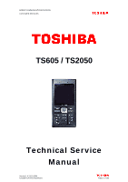
MOBILE COMMUNICATIONS DIVISION CUSTOMER SERVICES TS605 / TS2050 Technical Service Manual Version 1.0 22/11/2006 Created by Konrad Szombara Page 1 of 103 - Toshiba TS605 | Service Manual - Page 2
MOBILE COMMUNICATIONS DIVISION CUSTOMER SERVICES INDEX PAGE 1.0 GENERAL ADVICE 5 1.1 CUSTOMER CARE SOLUTIONS 6 1.2 ESD PROTECTION 7 2.0 HANDSET SPECIFICATION AND INTRODUCTION 8 2.1 HANDSET SPECIFICATION 9 2.1.1 HARDWARE 9 2.1.2 SOFTWARE 10 2.1.3 PHYSICAL 11 2.1.4 VIDEO 12 2.1.5 - Toshiba TS605 | Service Manual - Page 3
MOBILE COMMUNICATIONS DIVISION CUSTOMER SERVICES INDEX 5.0 SOFTWARE DOWNLOAD 5.1 SOFTWARE DOWNLOAD 5.1.1 DOWNLOAD CABLES 5.1.2 DOWNLOAD TOOL 5.1.3 EQUIPMENT SETTING 5.1.4 MAIN PROGRAM INTERFACE 5.1.5 BACKUP TOOL 6.0 SYSTEM MODULE AND USER INTERFACE 6.1 TECHNICAL DESCRIPTION 6.1.1 RF OVERVIEW 6.1.2 - Toshiba TS605 | Service Manual - Page 4
MOBILE COMMUNICATIONS DIVISION CUSTOMER SERVICES INDEX 7.0 TROUBLE SHOOTING 7.1 MAIN TROUBLE SHOOTING DIAGRAM 7.1.1 NO POWER UP 7.1.2 FLASH FAILED 7.1.3 WILL NOT READ SIM CARD 7.1.4 POOR SERVICE 7.1.5 WILL NOT CHARGE 7.1.6 LCD FAILURE 7.1.7 BUZZER FAULT 7.1.8 VIBRATOR FAULT 7.1.9 FAULTY KEYPAD 7.1. - Toshiba TS605 | Service Manual - Page 5
MOBILE COMMUNICATIONS DIVISION CUSTOMER SERVICES 1.0 GENERAL ADVICE Version 1.0 22/11/2006 Created by Konrad Szombara Page 5 of 103 - Toshiba TS605 | Service Manual - Page 6
MOBILE COMMUNICATIONS DIVISION CUSTOMER SERVICES 1.1 CUSTOMER CARE SOLUTIONS TECHNICAL DOCUMENTATION Warnings 1- Care within this service manual must remain confidential and should not be shared with any unknown 3rd party, without written consent from Toshiba MCD, UK. Cautions 1- Servicing and - Toshiba TS605 | Service Manual - Page 7
MOBILE COMMUNICATIONS DIVISION CUSTOMER SERVICES 1.2 ESD (Electro Static Discharge)PROTECTION SERVICE REQUIRMENTS 1- Toshiba require that all TPSV's ensure that the technicians work bench has sufficient ESD protection. 2- Accessories such as batteries, chargers, multimedia cards and sim cards can - Toshiba TS605 | Service Manual - Page 8
MOBILE COMMUNICATIONS DIVISION CUSTOMER SERVICES 2.0 HANDSET SPECIFICATION AND INTRODUCTION Version 1.0 22/11/2006 Created by Konrad Szombara Page 8 of 103 - Toshiba TS605 | Service Manual - Page 9
MOBILE COMMUNICATIONS DIVISION CUSTOMER SERVICES 2.1 HANDSET SPECIFICATION 2.2.1 HARDWARE Item Frequency Display Camera Citizen Bluetooth V1.2 Vender: CSR Chipset: BC3-ROM Support: v1.2 Power Class: Class 2 or 3 Max Size of data of phone memory : 350KB FM Radio IrDA Multimedia Chip Audio Codec - Toshiba TS605 | Service Manual - Page 10
SERVICES 2.1.2 SOFTWARE Item WAP MMS DRM IMPS Java Doja KVM JSR-75 PDA PIM & FC JSR-120 WMA 1.1 JSR-135 JSR-205 WMA 2.0 JSR-234 Advanced Multimedia Supplements JSR-248 Mobile Service : JSR-135 MMAPI (mobile multimedia API) + JSR-139 CLDC 1.1) TBD, define by Toshiba ExtendSI TBD Version 1.0 - Toshiba TS605 | Service Manual - Page 11
MOBILE COMMUNICATIONS DIVISION CUSTOMER SERVICES 2.1.3 PHYSICAL SPECIFICATION Item Description Detail Features Air Link Protocol GPRS EDGE Class10 ---- Physical Features Form Factor Dimension Weight Candy Bar 113*47*10.3mm 84g ( - Toshiba TS605 | Service Manual - Page 12
Support Interface MP3 MP3 ring tone Battery standby time Battery Voice talk time Battery Capacity Description Remark X8 BMP, JPEG, GIF, PNG CIF @ 15fps N/A CIF @ 15fps N/A N/A N/A N/A N/A N/A N/A N/A N/A Wolfson WM8976 AMR AMR/MP3(H/W)/AAC+ N/A Poly40 (TBD) I2S (MP3), ADI-AD6537 (ringtone - Toshiba TS605 | Service Manual - Page 13
COMMUNICATIONS DIVISION CUSTOMER SERVICES 2.1.5 OTHERS Item SIM STK Release 98 STK Release 99 STK Class SIM Lock CPHS USSD Multimedia Message WAP SMS SMS - Cell Broadcast EMS MMS i-Mode E-Mail DRM IMPS Mobile QQ PoC (Push to Talk) Data Exchange OBEX SynML DS SynML DM FOTA IrDA Description Remark - Toshiba TS605 | Service Manual - Page 14
-248 Mobile Service Architecture for CLDC Description N/A Yes Yes Yes N/A Yes Yes N/A Yes N/A Yes N/A N/A Yes JSR-185 Voice Recognition Speaker Dependent Speaker Independent Text to Speech USB Features USB drive Webcam PC software Others Image Stabilization Motion Detection Digital TV Support 3D - Toshiba TS605 | Service Manual - Page 15
MOBILE COMMUNICATIONS DIVISION CUSTOMER SERVICES 2.1.6 PRODUCT OVERVIEW The TS605 structure, even people whom are new to phones will find this very easy to use is used for the headset, the charger and connectivity via the PC suite types of file the handset supports. Another way to transfer files is - Toshiba TS605 | Service Manual - Page 16
MOBILE COMMUNICATIONS DIVISION CUSTOMER SERVICES 2.2 INTERFACES 2.2.1 SIM CARD INTERFACE Your SIM card identifies your phone on the network and stores your details, including your PIN, call history, and subscription information. It can also be used to store some phone phone to locate your battery room - Toshiba TS605 | Service Manual - Page 17
MOBILE COMMUNICATIONS DIVISION CUSTOMER SERVICES Version 1.0 22/11/2006 Created by Konrad Szombara Page 17 of 103 - Toshiba TS605 | Service Manual - Page 18
MOBILE COMMUNICATIONS DIVISION CUSTOMER SERVICES 2.2.2 MEMORY CARD INTERFACE Your Phones supports a microSD card up to 1GB. The memory card slot is located under the battery. The battery cover is located on the rear of the phone. Inserting / Removing the Memory slot Turn to the back of your phone to - Toshiba TS605 | Service Manual - Page 19
MOBILE COMMUNICATIONS DIVISION CUSTOMER SERVICES Version 1.0 22/11/2006 Created by Konrad Szombara Page 19 of 103 - Toshiba TS605 | Service Manual - Page 20
MOBILE COMMUNICATIONS DIVISION CUSTOMER SERVICES 2.2.3 BATTERY INTERFACE The battery included with your phone is not charged. Before you can switch on your phone for the first time, you need to install the phone's battery and charge it. Inserting or Changing the Battery To insert or change the - Toshiba TS605 | Service Manual - Page 21
MOBILE COMMUNICATIONS DIVISION CUSTOMER SERVICES 2.2.4 Charging the Battery To charge a battery: During charging, there will no indication on the phone screen. Please keep the phone charge for a white before you disconnect the charger. Disconnecting the charger To disconnect the charger, grip it - Toshiba TS605 | Service Manual - Page 22
MOBILE COMMUNICATIONS DIVISION CUSTOMER SERVICES 2.2.5 Charging Indicator The first time you charge your battery, you should leave it charging for 8 hours. The battery only achieves optimum performance after two or three complete charges. When the battery power is low, the phone starts beeping and - Toshiba TS605 | Service Manual - Page 23
MOBILE COMMUNICATIONS DIVISION CUSTOMER SERVICES 2.3 HANDSET UI 2.3.1 HANDSET DESCRIPTION Version 1.0 22/11/2006 Created by Konrad Szombara Page 23 of 103 - Toshiba TS605 | Service Manual - Page 24
MOBILE COMMUNICATIONS DIVISION CUSTOMER SERVICES 2.3.2 KEY FUNCTIONALITY Version 1.0 22/11/2006 Created by Konrad Szombara Page 24 of 103 - Toshiba TS605 | Service Manual - Page 25
MOBILE COMMUNICATIONS DIVISION CUSTOMER SERVICES Version 1.0 22/11/2006 Created by Konrad Szombara Page 25 of 103 - Toshiba TS605 | Service Manual - Page 26
CUSTOMER SERVICES 2.3.3 Display Concept - Main No. Icon 1 2 3 4 5 6 7 8 9 10 Version 1.0 22/11/2006 Created by Konrad Szombara Description Signal Strength (lower to high) Roaming Keypad lock Appointments Bluetooth (active/connecting) Phone set to mute/Vibrate Alarm Set Message indicator Battery - Toshiba TS605 | Service Manual - Page 27
MOBILE COMMUNICATIONS DIVISION CUSTOMER SERVICES 2.3.4 MAIN MENU Version 1.0 22/11/2006 Created by Konrad Szombara Page 27 of 103 - Toshiba TS605 | Service Manual - Page 28
MOBILE COMMUNICATIONS DIVISION CUSTOMER SERVICES Menu Structure Key Main Menu Settings Browser Tools 2nd Templates Messenger Cell Info Memory Status Settings Key Main Menu 2nd Level Entertainment Games Composer Contacts My Player My data Calls STK* Shortcuts View contacts View groups - Toshiba TS605 | Service Manual - Page 29
test the voice recording function. „ FM radio: test FM radio function. 3. Software Version: Check the current software version 4. DTM: For production test. Determine if DTMF function valid during calling. 5. Com port: „ AT-DATA: set phone jack for special D/L port, ex: IMEI burning. „ GENIE: for RD - Toshiba TS605 | Service Manual - Page 30
MOBILE COMMUNICATIONS DIVISION CUSTOMER SERVICES 3.0 MECHANICAL CONCEPT Version 1.0 22/11/2006 Created by Konrad Szombara Page 30 of 103 - Toshiba TS605 | Service Manual - Page 31
MOBILE COMMUNICATIONS DIVISION CUSTOMER SERVICES 3.1 Exploded View Version 1.0 22/11/2006 Created by Konrad Szombara Page 31 of 103 - Toshiba TS605 | Service Manual - Page 32
MOBILE COMMUNICATIONS DIVISION CUSTOMER SERVICES EXPLODED VIEW CONTINUED Version 1.0 22/11/2006 Created by Konrad Szombara Page 32 of 103 - Toshiba TS605 | Service Manual - Page 33
TBD 33VI5TC0I01 DQ663196502 2 BASE CASE ASSY VI5 SILVER 3 MIDDLE CASE ASSY VI5 4 RECEIVER (SPK 320OHM) 5 SPEAKER 8 OHM 97DB(0.5W,DSH929-001) 7 BATTERY COVER 8 CABLE ASSY VI1 ANTENNA 9 LCD SHIELD VI1 10 GLUE LCD SHIELD 11 MAIN LCD LENS BLACK 12 GLUE MAIN LCD LENS 13 KEYSET VI5 - Toshiba TS605 | Service Manual - Page 34
MOBILE COMMUNICATIONS DIVISION CUSTOMER SERVICES 3.3 SPARE PARTS - PHOTO Version 1.0 22/11/2006 Created by Konrad Szombara Page 34 of 103 - Toshiba TS605 | Service Manual - Page 35
MOBILE COMMUNICATIONS DIVISION CUSTOMER SERVICES 4.0 DISASSEMBLY AND REASSEMBLY PROCEDURE Version 1.0 22/11/2006 Created by Konrad Szombara Page 35 of 103 - Toshiba TS605 | Service Manual - Page 36
MOBILE COMMUNICATIONS DIVISION CUSTOMER SERVICES 4.1 DISASSEMBLY Purpose:Change defect mechanical parts Tools: Black Sticker, T5 and Tweezers T5 Tools :T5 and Tweezers and Black Sticker Tweezers Black Sticker Remove the Battery Cover Remove the Battery Version 1.0 22/11/2006 Created by Konrad - Toshiba TS605 | Service Manual - Page 37
MOBILE COMMUNICATIONS DIVISION CUSTOMER SERVICES Take out Car kit rubber Release 2 screws Using Black Sticker to lift up the Top Case from the Base Case. Version 1.0 22/11/2006 Created by Konrad Szombara Page 37 of 103 - Toshiba TS605 | Service Manual - Page 38
MOBILE COMMUNICATIONS DIVISION CUSTOMER SERVICES Using Black Sticker to lift up the Top Case form the right side. Using Black Sticker to lift up the Top Case from the left side. (be care do not damage the Bluetooth Antenna) Let the Top Case upward. And - Toshiba TS605 | Service Manual - Page 39
MOBILE COMMUNICATIONS DIVISION CUSTOMER SERVICES The Motor (vibrator) can be pulled up when use tweezers. Remove the receiver Release 2 screws of middle case Version 1.0 22/11/2006 Created by Konrad Szombara Page 39 of 103 - Toshiba TS605 | Service Manual - Page 40
MOBILE COMMUNICATIONS DIVISION CUSTOMER SERVICES Separate Key PCB from the Antenna Holder. Separate the Antenna Holder from Base case Use Black Sticker to raise the PCB module from the Base Case. Use Black Sticker to raise the PCB module from the Middle Case. Version 1.0 22/11/2006 Created by - Toshiba TS605 | Service Manual - Page 41
MOBILE COMMUNICATIONS DIVISION CUSTOMER SERVICES tear off mylar of Speaker Remove the speaker. (Carefully not to damage the SPK's pin.) Version 1.0 22/11/2006 Created by Konrad Szombara Page 41 of 103 - Toshiba TS605 | Service Manual - Page 42
MOBILE COMMUNICATIONS DIVISION CUSTOMER SERVICES Detach the Key PCB coaxial cable head from the Key PCB & M/B Version 1.0 22/11/2006 Created by Konrad Szombara Page 42 of 103 - Toshiba TS605 | Service Manual - Page 43
MOBILE COMMUNICATIONS DIVISION CUSTOMER SERVICES 4.2 REASSEMBLY Assemble Middle Case on Base Case Make sure hook on the position as shown Assemble Antenna Holder on Base Case Version 1.0 22/11/2006 Created by Konrad Szombara Page 43 of 103 - Toshiba TS605 | Service Manual - Page 44
MOBILE COMMUNICATIONS DIVISION CUSTOMER SERVICES Tear off paper of speaker. Place the Speaker on the Base Case. (remind:be care the pins of speaker, don't damage) Stick Mylar on Speaker Stick Mylar on USB Conn as shown Version 1.0 22/11/2006 Created by Konrad Szombara Page 44 of 103 - Toshiba TS605 | Service Manual - Page 45
MOBILE COMMUNICATIONS DIVISION CUSTOMER SERVICES Mount the Key PCB coaxial cable head on the Key PCB & M/B. Tear off protect film of CMOS Version 1.0 22/11/2006 Created by Konrad Szombara Page 45 of 103 - Toshiba TS605 | Service Manual - Page 46
MOBILE COMMUNICATIONS DIVISION CUSTOMER SERVICES Assemble USB into Base Case then assemble M/B to base case as shown Tear off tape paper of base case as shown then assemble K/B on base case Pls - Toshiba TS605 | Service Manual - Page 47
MOBILE COMMUNICATIONS DIVISION CUSTOMER SERVICES Tighten 2 screws on middle case (Torque: 0.5+/0.1kgsf/cm2) Tear off tape paper of Receiver then assemble on Top Case Tear off tape paper of Motor then assemble on Top Case as shown Version 1.0 22/11/2006 Created by Konrad Szombara Page 47 of 103 - Toshiba TS605 | Service Manual - Page 48
MOBILE COMMUNICATIONS DIVISION CUSTOMER SERVICES Place Keyset on Top Case Assemble the Top Case with the Base Case as shown. (Be care the Motor line) Take care and do not damage Bluetooth Antenna Version 1.0 22/11/2006 Created by Konrad Szombara Page 48 of 103 - Toshiba TS605 | Service Manual - Page 49
MOBILE COMMUNICATIONS DIVISION CUSTOMER SERVICES Position Top Case hook as shown Tighten 2 screws (Torque: 0.5+/0.1kgsf/cm2) Version 1.0 22/11/2006 Created by Konrad Szombara Page 49 of 103 - Toshiba TS605 | Service Manual - Page 50
MOBILE COMMUNICATIONS DIVISION CUSTOMER SERVICES Tear off tape paper of Main Lens Glue Stick on the main Lens shielding Clean the LCD and Main Lens Then assemble LCD Main Lens Tear Cmos lens tape paper Version 1.0 22/11/2006 Created by Konrad Szombara Page 50 of 103 - Toshiba TS605 | Service Manual - Page 51
MOBILE COMMUNICATIONS DIVISION CUSTOMER SERVICES Stick CMOS Lens Assemble Carkit Rubber as shown Install the Battery Version 1.0 22/11/2006 Created by Konrad Szombara Page 51 of 103 - Toshiba TS605 | Service Manual - Page 52
MOBILE COMMUNICATIONS DIVISION CUSTOMER SERVICES Position the Battery Cover Version 1.0 22/11/2006 Created by Konrad Szombara Page 52 of 103 - Toshiba TS605 | Service Manual - Page 53
MOBILE COMMUNICATIONS DIVISION CUSTOMER SERVICES 5.0 SOFTWARE DOWNLOAD Version 1.0 22/11/2006 Created by Konrad Szombara Page 53 of 103 - Toshiba TS605 | Service Manual - Page 54
MOBILE COMMUNICATIONS DIVISION CUSTOMER SERVICES 5.1 SOFTWARE DOWNLOAD 5.1.1 DOWNLOAD CABLES Version 1.0 22/11/2006 Created by Konrad Szombara Page 54 of 103 - Toshiba TS605 | Service Manual - Page 55
MOBILE COMMUNICATIONS DIVISION CUSTOMER SERVICES 5.1.2 DOWNLOAD TOOL Core Software Mapping Download Language Pack Header (encrypted) Download Setting (Mem. address, FFS...), PMC code Agent (Encrypted Raw Data) Target (Encrypted Raw Data) MBF file Version 1.0 22/ - Toshiba TS605 | Service Manual - Page 56
MOBILE COMMUNICATIONS DIVISION CUSTOMER SERVICES 5.1.3 EQUIPMENT SETTING PC Handset D/L Cable • Keep handset off before downloading software • Endure that battery capacity is suitable for duration of download procedure Version 1.0 22/11/2006 Created by Konrad Szombara Page 56 of 103 - Toshiba TS605 | Service Manual - Page 57
MOBILE COMMUNICATIONS DIVISION CUSTOMER SERVICES 5.1.4 MAIN PROGRAM INTERFACE Version 1.0 22/11/2006 Created by Konrad Szombara Page 57 of 103 - Toshiba TS605 | Service Manual - Page 58
DIVISION CUSTOMER SERVICES When you have connected the cable to the handset, switch it on and the USB connection will detect automatically. 1 4 23 1 - Load the specific configuration file and check the configuration 2 - Wait until "Press Power is showing 3 - Long press mobile power key - Toshiba TS605 | Service Manual - Page 59
MOBILE COMMUNICATIONS DIVISION CUSTOMER SERVICES 5.1.5 BACKUP TOOL Program Functions - Clear: Erase all user data - Restore: restore user data to handset Backup Tool Procedure 1 - Insert download cable and keep mobile power off 2 - Execute the Backup Tool Program from the Start menu 3 - Select your - Toshiba TS605 | Service Manual - Page 60
MOBILE COMMUNICATIONS DIVISION CUSTOMER SERVICES 6.0 SYSTEM MODULE AND USER INTERFACE Version 1.0 22/11/2006 Created by Konrad Szombara Page 60 of 103 - Toshiba TS605 | Service Manual - Page 61
COMMUNICATIONS DIVISION CUSTOMER SERVICES 6.1 TECHNICAL DESCRIPTION 6.1.1 RF OVERVIEW INTRODUCTION General Specifications The telephone is a Tri-Band product. The transmit and receive bands for the mobile are given in the table below: E-GSM 900 GSM 1800 PCS 1900 TX 880-915 MHz 1710-1785 MHz - Toshiba TS605 | Service Manual - Page 62
MOBILE COMMUNICATIONS DIVISION CUSTOMER SERVICES 6.1.2 RF FUNCTION BLOCK DIAGRAM SKY77328 26MHz XTAL SKY74117 Version 1.0 22/11/2006 Created by Konrad Szombara Page 62 of 103 - Toshiba TS605 | Service Manual - Page 63
MOBILE COMMUNICATIONS DIVISION CUSTOMER SERVICES 6.1.3 FREQUENCY PLAN The TX frequency plan is shown below TX frequency plan is designed for embedded type and this design is fabricated on a FPC. It supports triple band applications. Version 1.0 22/11/2006 Created by Konrad Szombara Page 63 of 103 - Toshiba TS605 | Service Manual - Page 64
MOBILE COMMUNICATIONS DIVISION CUSTOMER SERVICES 6.1.4 TRANSMITTER SKY77328 SKY74117 Figure Transmitter block diagram TX path is a translation loop architecture consisting of an IQ modulator, integrated high power VCO, offset mixer, programmable - Toshiba TS605 | Service Manual - Page 65
MOBILE COMMUNICATIONS DIVISION CUSTOMER SERVICES 6.1.5 RECEIVER GSM DCS PCS Figure Receiver block diagram RX path is a direction down conversion architecture that eliminates the need for Intermediate Frequency (IF) components. The - Toshiba TS605 | Service Manual - Page 66
MOBILE COMMUNICATIONS DIVISION CUSTOMER SERVICES 6.2 BASEBAND OVERVIEW 6.2.1 INTRODUCTION The baseband block of the handset performs the following functions: Equalization Channel coding / decoding Speech coding / decoding Data Encryption Layer 1, 2 and 3 software tasks Man Machine interface (MMI) - Toshiba TS605 | Service Manual - Page 67
MOBILE COMMUNICATIONS DIVISION CUSTOMER SERVICES Digital Baseband Processor GSM processor Package ADI AD6527B 204 1.8V Data and Program SRAM Program Instruction Cache Enhanced full rate and Half Rate Speech Encoding / Decoding Capable of Supporting PDC,AMR Speech Algorithms 3. Peripheral Subsystem - Toshiba TS605 | Service Manual - Page 68
), AWB (Auto White Balance), digital room and some image special effects. The maximum supported resolution is VGA (640*480). AIT811 also contains many features, which are suitable for mobile phone camera applications including hardware JPEG coding/encoding, 2D graphic engine and hardware color DSP - Toshiba TS605 | Service Manual - Page 69
MOBILE COMMUNICATIONS DIVISION CUSTOMER SERVICES 6.3 SWITCHES 6.3.1 KEYPAD The keypad matrix contains 4 rows and 5 columns, allowing 20 keys to be scanned. When a key is pressed, a keypad interrupt is generated. Then system - Toshiba TS605 | Service Manual - Page 70
DIVISION CUSTOMER SERVICES 6.4 AUDIO SYSTEM Figure Audio system block diagram AD6537B is a complete mixed-signal baseband processor that combines all of the data converters and power supply regulators required for GSM 900 /GSM 850 /DCS 1800 / PCS 1900 mobile on a single device, including - Toshiba TS605 | Service Manual - Page 71
MOBILE COMMUNICATIONS DIVISION CUSTOMER SERVICES 6.4.1 VOICE BAND CODEC Chipset ADI AD6537B Package 148- kHz Monophonic DAC Power Amplifiers Power Management Section Voltage Regulators Battery Charger Battery Protection Digital Processor Interface Control, Baseband, and Audio Serial Ports - Toshiba TS605 | Service Manual - Page 72
MOBILE COMMUNICATIONS DIVISION CUSTOMER SERVICES About handset power management, AD6537B is designed to supply all digital signals and VABB supplies all the analog power. VRTC is used to charge the RTC battery for real time clock module, and VCTCXO is the power source of the system clock. A hardware - Toshiba TS605 | Service Manual - Page 73
MOBILE COMMUNICATIONS DIVISION CUSTOMER SERVICES 6.4.4 SPEAKER A second speaker is housed in the back case Memory VMEM VBAT NReset RTC Circuit Power Management part of AD6537 VRTC VCORE Battery VABB VMEM Charging Circuit SIMVCC 26MHz AD6527 VCORE VMEM SIM Circuit Figure Power Management - Toshiba TS605 | Service Manual - Page 74
MOBILE COMMUNICATIONS DIVISION CUSTOMER SERVICES 6.5.1 POWER ON SEQUENCE When the user presses the power key, KEYON pin of AD6537B is pulled low; all the LDOs required for system boot will - Toshiba TS605 | Service Manual - Page 75
MOBILE COMMUNICATIONS DIVISION CUSTOMER SERVICES 6.5.2 POWER SOURCE The battery used is a single Lithium-Ion (Li-Ion) cell with a nominal voltage of 3.7 V and 700-mAh capacity. T Li-Ion type of battery user or software. If user presses the power-on key (KEYON pin of AD6537B),or a charger is plugged( - Toshiba TS605 | Service Manual - Page 76
MOBILE COMMUNICATIONS DIVISION CUSTOMER SERVICES TCXO Regulator (VTCXO): 2.8 V The TCXO regulator is intended asserted. RTC Regulator (VRTC): 1.8 V The RTC regulator is used to charge the RTC backup battery needed by real-time clock module. It also provide the power source directly to the RTC module - Toshiba TS605 | Service Manual - Page 77
MOBILE COMMUNICATIONS DIVISION CUSTOMER SERVICES 7.0 TROUBLESHOOTING Version 1.0 22/11/2006 Created by Konrad Szombara Page 77 of 103 - Toshiba TS605 | Service Manual - Page 78
MOBILE COMMUNICATIONS DIVISION CUSTOMER SERVICES 7.1 MAIN TROUBLESHOOTING DIAGRAM Version 1.0 22/11/2006 Created by Konrad Szombara Page 78 of 103 - Toshiba TS605 | Service Manual - Page 79
MOBILE COMMUNICATIONS DIVISION CUSTOMER SERVICES 7.1.1 NO POWER UP Cause : PCB dead or Part jammed Phone Version 1.0 22/11/2006 Created by Konrad Szombara Page 79 of 103 - Toshiba TS605 | Service Manual - Page 80
MOBILE COMMUNICATIONS DIVISION CUSTOMER SERVICES 7.1.2 FLASH FAILED Cause : PCB dead or Min. USB has broken Version 1.0 22/11/2006 Created by Konrad Szombara Page 80 of 103 - Toshiba TS605 | Service Manual - Page 81
MOBILE COMMUNICATIONS DIVISION CUSTOMER SERVICES 7.1.3 WILL NOT READ SIMCARD Cause : PCB dead or SIM card holder has broken Version 1.0 22/11/2006 Created by Konrad Szombara Page 81 of 103 - Toshiba TS605 | Service Manual - Page 82
MOBILE COMMUNICATIONS DIVISION CUSTOMER SERVICES 7.1.4 LOW / NO SERVICE Cause : PCB dead or Antenna has broken Low Receiving Signal or can not connect Network Service Provider NO Check SIM card setting right? Refer to (Phone can not read SIM card) Yes Yes Check Antenna touching correct ? Yes - Toshiba TS605 | Service Manual - Page 83
MOBILE COMMUNICATIONS DIVISION CUSTOMER SERVICES 7.1.5 WILL NOT CHARGE Cause: PCB dead or Mini. USB has broken Version 1.0 22/11/2006 Created by Konrad Szombara Page 83 of 103 - Toshiba TS605 | Service Manual - Page 84
MOBILE COMMUNICATIONS DIVISION CUSTOMER SERVICES 7.1.6 FAULTY LCD Cause: PCB dead or LCD module has broken Illumination Testing Restore factory setting Fail NO Re-Download Refer to (Updating program is failed) - Toshiba TS605 | Service Manual - Page 85
MOBILE COMMUNICATIONS DIVISION CUSTOMER SERVICES 7.1.7 FAULTY BUZZER Cause: PCB dead or Buzzer/Receiver has broken Buzzer Testing Restore factory setting Fail NO Re-Download Refer to (Updating program is failed) - Toshiba TS605 | Service Manual - Page 86
MOBILE COMMUNICATIONS DIVISION CUSTOMER SERVICES 7.1.8 FAULTY VIBRA MOTOR Cause: PCB dead or Vibrator has broken Version 1.0 22/11/2006 Created by Konrad Szombara Page 86 of 103 - Toshiba TS605 | Service Manual - Page 87
MOBILE COMMUNICATIONS DIVISION CUSTOMER SERVICES 7.1.9 FAULTY KEYPAD Cause: PCB dead or Keypads has broken Keypads Testing Restore factory setting Fail Re-Download NO Refer to (Updating program is failed) Yes - Toshiba TS605 | Service Manual - Page 88
MOBILE COMMUNICATIONS DIVISION CUSTOMER SERVICES 7.1.10 RTC FAULTY Cause: PCB dead or RTC battery has broken RTC status Testing Restore factory setting Fail Re-Download NO Refer to (Updating program is failed) Yes Check (BAT101) of PCBA 0.8 v Yes PCBA - Toshiba TS605 | Service Manual - Page 89
MOBILE COMMUNICATIONS DIVISION CUSTOMER SERVICES 7.1.11 MIC AND SPEAKER FAULTY Cause: PCB dead or Microphone / Speaker has broken Microphone Speaker Testing Earphone Fail , check Mini. USB port Refer to (Charging can not work) Restore factory setting Fail Re-Download NO Refer to (Updating - Toshiba TS605 | Service Manual - Page 90
MOBILE COMMUNICATIONS DIVISION CUSTOMER SERVICES 7.1.12 LCD ERROR Cause: PCB dead or LCD module has broken LCD Testing Restore factory setting Fail Re-Download No Refer to (Updating program is - Toshiba TS605 | Service Manual - Page 91
MOBILE COMMUNICATIONS DIVISION CUSTOMER SERVICES 7.1.13 CAMERA FAULTY Cause: PCB dead or CMOS has broken Camera Testing Restore factory setting Fail Re-Download No Yes Refer to (Updating program is - Toshiba TS605 | Service Manual - Page 92
Mobile Communications Division Customer Services 7.2 CONNECTORS 7.2.1 Connectors on Board I USB Connector J500 RTC BAT 101 Battery Connector J201 Version 1.0 14/08/2006 Created by Konrad Szombara Page 92 of 103 - Toshiba TS605 | Service Manual - Page 93
Mobile Communications Division Customer Services 7.2.2 ACF CONNECTIONS LCD Connector J402 CMOS Connector J401 KEY FPC Conn J302 Version 1.0 14/08/2006 Created by Konrad Szombara Page 93 of 103 - Toshiba TS605 | Service Manual - Page 94
Mobile Communications Division Customer Services 7.2.3 MAIN BASEBAND IC ON PCB Backend IC (AIT811) U403 Memory 256+64mb U102 GSM Processor ADI 6527 U101 Power Controller ADI6538B U201 Version 1.0 14/08/2006 Created by Konrad Szombara Page 94 of 103 - Toshiba TS605 | Service Manual - Page 95
Mobile Communications Division Customer Services MAIN BASEBAND IC's continued: Melody IC U503 Version 1.0 14/08/2006 Created by Konrad Szombara Page 95 of 103 - Toshiba TS605 | Service Manual - Page 96
Mobile Communications Division Customer Services 7.2.4 MAIN RF IC's ON PCB PA (SKY77328) U1101 BlueTooth IC U1002 Transceiver (SKY74117) U1201 Version 1.0 14/08/2006 Created by Konrad Szombara Page 96 of 103 - Toshiba TS605 | Service Manual - Page 97
Mobile Communications Division Customer Services 7.2.5 CONNECTORS ON KEYPAD MODULE SIM HOLDER J600 FLASH CARD HOLDER J1 Version 1.0 14/08/2006 Created by Konrad Szombara Page 97 of 103 - Toshiba TS605 | Service Manual - Page 98
Mobile Communications Division Customer Services 7.3 ACF - ANISOTROPIC CONDUCTIVE FILM ACF is a reliable, cheap been used for years on technologies such as Laptop's. How many LCD's have you seen go blank on a phone and how many on a Laptop? There are 2 ways of bonding. You can use ACF Tape and Shown - Toshiba TS605 | Service Manual - Page 99
Mobile Communications Division Customer Services The bonding particles are the small white dots that you can see on the clear tape. Or you can use ACP or Anisotropic Conductive Paste. - Toshiba TS605 | Service Manual - Page 100
Mobile Communications Division Customer Services Handset Specific Jig Paste This equipment along with the correct materials and procedures MUST be used for ACF parts replacement. Version 1.0 14/08/2006 Created by Konrad Szombara Page 100 of 103 - Toshiba TS605 | Service Manual - Page 101
Mobile Communications Division Customer Services The following pictures are for equipment that MUST NOT be used for ACF replacement and as such would invalidate any such warranty with Toshiba: This is not acceptable as it is open to human error along with the fact that it is non ESD compliant and - Toshiba TS605 | Service Manual - Page 102
Mobile Communications Division Customer Services Step 2 - Smear ACF rework dissolvent around the ACF with a cotton swab. Step 3 - Wait for the underfill to get hard. This will take approximately 30-40 minutes. Use black stick to clean the underfill away. Then clean with grain alcohol. Version 1.0 - Toshiba TS605 | Service Manual - Page 103
Mobile Communications Division Customer Services 7.4 LABEL SPECIFICATION Please note that the label design can be different, dependant on the customer. Version 1.0 14/08/2006 Created by Konrad Szombara Page 103 of 103
-
 1
1 -
 2
2 -
 3
3 -
 4
4 -
 5
5 -
 6
6 -
 7
7 -
8
-
9
-
10
-
11
-
12
-
13
-
14
-
15
-
16
-
17
-
18
-
19
-
20
-
21
-
22
-
23
-
24
-
25
-
26
-
27
-
28
-
29
-
30
-
31
-
32
-
33
-
34
-
35
-
36
-
37
-
38
-
39
-
40
-
41
-
42
-
43
-
44
-
45
-
46
-
47
-
48
-
49
-
50
-
51
-
52
-
53
-
54
-
55
-
56
-
57
-
58
-
59
-
60
-
61
-
62
-
63
-
64
-
65
-
66
-
67
-
68
-
69
-
70
-
71
-
72
-
73
-
74
-
75
-
76
-
77
-
78
-
79
-
80
-
81
-
82
-
83
-
84
-
85
-
86
-
87
-
88
-
89
-
90
-
91
-
92
-
93
-
94
-
95
-
96
-
97
-
98
-
99
-
100
-
101
-
102
-
103
 |
 |
MOBILE COMMUNICATIONS DIVISION
CUSTOMER SERVICES
Version 1.0 22/11/2006
Created by Konrad Szombara
Page 1 of 103
TS605 / TS2050
Technical Service
Manual