Troy-Bilt Storm 3090 Operation Manual
Troy-Bilt Storm 3090 Manual
 |
View all Troy-Bilt Storm 3090 manuals
Add to My Manuals
Save this manual to your list of manuals |
Troy-Bilt Storm 3090 manual content summary:
- Troy-Bilt Storm 3090 | Operation Manual - Page 1
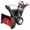
Safe Operation Practices • Set-Up • Operation • Maintenance • Service • Troubleshooting • Warranty Operator's Manual Two-Stage Snow Thrower - Storm 2410, 2620, 2840 & 3090XP WARNING READ AND FOLLOW ALL SAFETY RULES AND INSTRUCTIONS IN THIS MANUAL BEFORE ATTEMPTING TO OPERATE THIS MACHINE. FAILURE - Troy-Bilt Storm 3090 | Operation Manual - Page 2
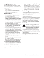
To The Owner 1 Thank You Thank you for purchasing a Troy-Bilt Snow Thrower. It was carefully engineered to provide excellent performance when properly operated and maintained. Please read this entire manual prior to operating the equipment. It instructs you how to safely and easily set up, operate - Troy-Bilt Storm 3090 | Operation Manual - Page 3
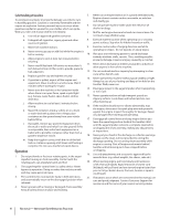
other loose clothing, which could become entangled in moving parts. Wear footwear which will improve footing on slippery surfaces. 3. Use a grounded three-wire extension cord and receptacle for all machines with electric start engines. 4. Adjust auger housing height to clear gravel or crushed rock - Troy-Bilt Storm 3090 | Operation Manual - Page 4
12. Do not overload machine capacity by attempting to clear g. Replace gasoline cap and tighten securely. snow at too fast of a rate. h. If gasoline is spilled, wipe it off the engine and equipment. Move machine to another area. Wait 5 minutes before starting the engine. 13. Never operate this - Troy-Bilt Storm 3090 | Operation Manual - Page 5
dryer etc. 11. Always refer to the operator's manual for proper instructions on off-season storage. 12. Check fuel line, tank, cap, and fittings frequently for cracks or leaks. Replace if necessary. 13. Do not crank engine with spark plug removed. 14. According to the Consumer Products Safety - Troy-Bilt Storm 3090 | Operation Manual - Page 6
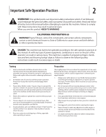
HOT SURFACE Engine parts, especially the muffler, become extremely hot during operation. Allow engine and muffler to cool before touching. warning! Your Responsibility-Restrict the use of this power machine to persons who read, understand and follow the warnings and instructions in this manual and - Troy-Bilt Storm 3090 | Operation Manual - Page 7
Set-Up 3 Contents of Carton • One Snow Thrower • One Snow Thrower Operator's Manual • One Engine Manual • Two Replacement Auger Shear Pins • One Chute Assembly (Model 2410) • One Product Registration Card • One Chute Control Rod (Models 2620, 2840 and 3090XP) Assembly Handle 1. Place the shift - Troy-Bilt Storm 3090 | Operation Manual - Page 8
secure. See Fig. 3-4. NOTE: If the flange keepers will not easily click into place, use the palm of your hand to apply swift, firm pressure to the back of each. Chute Assembly and Directional Control (Models 2620, 2840 and 3090XP) 1. Remove cotter pin, wing nut and hex screw from chute control head - Troy-Bilt Storm 3090 | Operation Manual - Page 9
by Figure 3-10 hand to face forward. The holes in the chute control input will be facing up. See Fig. 3-9. 6. Insert the chute control rod into the trigger on the joystick. NOTE: The chute control rod will fit snuggly into the pinion gear. Support the rear of the dash panel with one hand Chute - Troy-Bilt Storm 3090 | Operation Manual - Page 10
Shear Pins A pair of replacement auger shear pins and bow tie cotter pins are included with your snow thrower. Store them in your snow thrower's dash panel until needed. See Fig. 3-14. Figure 3-14 Figure 3-12 8. Finish securing chute control head to chute support bracket with wing nut, clevis pin - Troy-Bilt Storm 3090 | Operation Manual - Page 11
: The upper chute on models 2840 and 3090XP is also controlled by the 4-way Chute Directional Control. See Fig. 4-1. The distance snow is thrown can be adjusted by changing the angle of the chute assembly. To do so: 1. Stop the engine. Refer to the Engine Operator's Manual. Remove the key from the - Troy-Bilt Storm 3090 | Operation Manual - Page 12
. It should NOT be tight. 2. In a well-ventilated area, start the snow thrower engine. Refer to Engine Operator's Manual. 3. While standing in the operator's position (behind the snow thrower), engage the auger. 4. Allow the auger to remain engaged for approximately ten (10) seconds before releasing - Troy-Bilt Storm 3090 | Operation Manual - Page 13
Auger Control Heated Grips † Steering Trigger Control † Standard Chute Directional Control † Augers Skid Shoe † If Equipped Figure 4-1 Snow thrower for hard-packed snow. Adjust downward Augers When engaged, the augers rotate and draw snow into the auger Assembly Snow drawn into the auger housing - Troy-Bilt Storm 3090 | Operation Manual - Page 14
grip against the handle to engage the augers and start snow throwing action. Release to stop. Drive Control / Auger Clutch Lock The chute directional control is located on left side of the snow thrower. To change the direction in which snow is thrown, rotate chute directional control. 2-Way - Troy-Bilt Storm 3090 | Operation Manual - Page 15
or to the left. • To change the angle/distance which snow is thrown, pivot the joy-stick auger housing, reinsert the key and start the snow thrower's engine. While standing in the operator's position (behind the snow thrower), engage the auger control for a few seconds to clear any remaining snow - Troy-Bilt Storm 3090 | Operation Manual - Page 16
NEVER replace the auger shear pins with anything other than OEM Part No. 738-04124A replacement shear pins. Any damage to the auger gearbox or other components as a result of failing to do so will NOT be covered by your snow thrower's warranty. warning! Always turn off the snow thrower's engine and - Troy-Bilt Storm 3090 | Operation Manual - Page 17
Maintenance & Adjustments 6 Maintenance Engine Refer to the Engine Operator's Manual. Shave Plate and Skid Shoes The shave plate and skid shoes on the bottom of the snow thrower are subject to wear. They should be checked periodically and replaced when necessary. NOTE: Deluxe skid shoes (on select - Troy-Bilt Storm 3090 | Operation Manual - Page 18
shear pins from the auger cable or if the snow thrower's drive is disengaging Shut off the engine as instructed in the separate engine manual. 2. Loosen the Auger Control Refer to the Assembly and Set-up section for instructions on adjusting the auger control cable. 18 Section 6 - Maintenance - Troy-Bilt Storm 3090 | Operation Manual - Page 19
Figure 6-6 3. Reinsert the cotter pin through this hole and the chute control rod. See Fig. 6-6. Figure 6-7 2. Retighten the nuts. Off-Season Storage If the snow thrower will not be used for 30 days or longer, follow the storage instructions below. 1. Run the engine until the fuel tank is empty - Troy-Bilt Storm 3090 | Operation Manual - Page 20
Service 7 Belt Replacement Auger Belt To remove and replace your snow thrower's auger belt, proceed as follows: 4. Carefully pivot the snow thrower up and forward so that it rests on the auger housing. 5. Remove the frame cover from the underside of the snow thrower by removing the self-tapping - Troy-Bilt Storm 3090 | Operation Manual - Page 21
7. Remove the belt from around the auger pulley, and slip the Drive Belt belt between the support bracket and the auger pulley. See Fig. 7-5. To remove and replace your snow thrower's drive belt, proceed as follows: 1. To prevent spillage, remove all fuel from tank by running engine until it - Troy-Bilt Storm 3090 | Operation Manual - Page 22
to replace the snow thrower's friction wheel rubber. See an authorized Service Dealer to have the friction wheel rubber replaced or phone Customer Support as instructed on page 2 for information on ordering a Service Manual. To inspect the friction wheel, proceed as follows: 1. Allow the engine to - Troy-Bilt Storm 3090 | Operation Manual - Page 23
reverse order to reassemble to the snow thrower frame and lightly tap the shaft pin is in place in the bearing housing. See Fig. 7-9 inset. 5. After replacing the friction wheel, perform the Drive Control test on page 18 in the Maintenance and Adjustments section. Figure 7-10 Section 7 - Service - Troy-Bilt Storm 3090 | Operation Manual - Page 24
damaged. 5. Shear pin(s) sheared. 1. Chute assembled incorrectly. 1. Adjust drive control cable. Refer to Maintenance & Adjustments section. 2. Replace drive belt. Refer to Service section 3. Replace friction wheel. Refer to Service section. 1. Stop engine immediately and disconnect spark plug wire - Troy-Bilt Storm 3090 | Operation Manual - Page 25
Plate (Storm 2840) Shave Plate ((Storm 3090XP) 731-05632 Key 951-10292 Spark Plug Phone (800) 828-5500 to order replacement parts or a complete Parts Manual (have your full model number and serial number ready). Parts Manual downloads are also available free of charge at www.troybilt.com. 25 - Troy-Bilt Storm 3090 | Operation Manual - Page 26
number and serial number ready). Model Number Description 753-05762A OEM-390-679 490-241-0010 OEM-390-995 490-241-Y014 *Not compatible with Storm 2410. Heated Grips* Drift Cutter Kit Polymer Skid Shoe Kit Snow Thrower Protective Cover Troy-Bilt Snow Thrower Maintenance Kit 26 - Troy-Bilt Storm 3090 | Operation Manual - Page 27
Notes 11 27 - Troy-Bilt Storm 3090 | Operation Manual - Page 28
maintenance, alteration, vandalism, theft, fire, water, or damage because of other peril or natural disaster. Damage resulting from the installation or use of any part, accessory or attachment not approved by Troy-Bilt for use with the product(s) covered by this manual will void your warranty - Troy-Bilt Storm 3090 | Operation Manual - Page 29
Máquina quitanieve de dos etapas - Storm 2410, 2620, 2840 & 3090XP ADVERTENCIA LEA Y SIGA TODAS LAS INSTRUCCIONES DE ESTE MANUAL ANTES DE PONER EN FUNCIONAMIENTO ESTA MÁQUINA. SI NO RESPETA ESTAS INSTRUCCIONES PUEDE PROVOCAR LESIONES PERSONALES. TROY-BILT LLC, P.O. BOX 361131 CLEVELAND, OHIO - Troy-Bilt Storm 3090 | Operation Manual - Page 30
Troy-Bilt se encuentran en esta página. Queremos garantizar su entera satisfacción en todo momento. En este manual operador y mire hacia la parte inferior de la sección trasera troybilt.com ◊ Llame a un representante de Asistencia al Cliente al (800) 828-5500 ó (330) 558-7220 ◊ Escríbanos a Troy-Bilt - Troy-Bilt Storm 3090 | Operation Manual - Page 31
: Esta máquina está diseñada para ser utilizada respetando las normas de seguridad contenidas en este manual. Al igual que con cualquier tipo de equipo motorizado, un descuido o error por parte del operador puede producir lesiones graves. Esta máquina es capaz de amputar dedos, manos y pies y de - Troy-Bilt Storm 3090 | Operation Manual - Page 32
impulsor es un en marcha excepto en los casos específicamente recomendados en el manual del operador. 7. Deje que el motor y la máquina se adapten a apague el motor y permanezca detrás de las manijas hasta que todas las partes móviles se hayan detenido. 19. Use sólo uniones y accesorios aprobados - Troy-Bilt Storm 3090 | Operation Manual - Page 33
seguridad, verifique frecuentemente todos los componentes y reemplácelos sólo con partes de los fabricantes de equipos originales (OEM). "¡El uso de hornos, secadores de ropa, etc. 11. Consulte siempre el manual del operador para obtener instrucciones adecuadas para el almacenamiento fuera de - Troy-Bilt Storm 3090 | Operation Manual - Page 34
seguridad internacionales que pueden aparecer en este producto. Lea el manual del operador para obtener la información terminada sobre seguridad, eléctrico del motor en la lluvia. ADVERTENCIA - SUPERFICIE CALIENTE Las partes del motor, especialmente el silenciador, llega a ser muy caliente durante - Troy-Bilt Storm 3090 | Operation Manual - Page 35
Montaje y Configuración Contenido de la caja • Una máquina quitanieve • Un Manual del Operador de la Máquina Quitanieve • Un Manual del Motor • Dos pasadores de cuchilla de barrena de repuesto • Varilla hexagonal Montaje Manija 1. Coloque la palanca de cambios en la posición de avance (F) 6. 2. - Troy-Bilt Storm 3090 | Operation Manual - Page 36
2. Cierre a los guardas de reborde para asegurar la asamblea Montaje del canal (Modelos 2620, 2840, y 3090XP) de tobogán a la base del tobogán. Los guardas de reborde harán clic en el lugar cuando aseguran apropiadamente. 1. Retire el pasador de chaveta, la - Troy-Bilt Storm 3090 | Operation Manual - Page 37
tolva de Vista desde arriba entrada Figura 3-9 Figura 3-11 Nota: La barra hexagonal se ajusten perfectamente en el engranaje del piñón. Apoyo a la parte trasera del panel de instrumentos con una mano mientras inserta la varilla hexagonal con la otra mano para asegurar la barra hexagonal se inserta - Troy-Bilt Storm 3090 | Operation Manual - Page 38
estén adecuadamente dirigidos a través de la guía de cables de la parte superior del motor. Algunos modelos tienen sólo un cable para dirigir por la 13. La herramienta de limpieza del canal viene de fábrica ajustada a la parte superior de la caja de la barrena con un pasador de ensamblado y una - Troy-Bilt Storm 3090 | Operation Manual - Page 39
de las mismas. 3. Vuelva a ajustar bien las tuercas y los pernos. Asamblea del canal (Modelos 2410 & 2620) NOTA: La asamblea del canal en los modelos 2840 y 3090XP es controlada por la 4-forma direccional del canal de control. Vea la fig. 4-1. Se lanza la nieve de la distancia puede ser ajustada - Troy-Bilt Storm 3090 | Operation Manual - Page 40
el motor de la máquina quitanieve. Consulte la sección Encendido del motor en el manual de motor. 3. Asegúrese de que el regulador se encuentra en la posición posición del operador y apague el motor. Espere a que TODAS las partes móviles se detengan antes de volver a ajustar el control de la barrena - Troy-Bilt Storm 3090 | Operation Manual - Page 41
Controles y Características Control de Transmisión Palanca de Cambios † Montaje del Canal Herramienta de Limpieza del Canal Faro Delantero † 4 Control del Canal de Dos/Cuatro Direcciones † Control de la Barrena Agarre Termico † Control Disparador del Manejo † Control direccional del canal † - Troy-Bilt Storm 3090 | Operation Manual - Page 42
la nieve, gire la palanca de mando hacia adelante o atrás. Para activar los agarres térmicos, mueva el interruptor que se encuentra en la parte posterior del panel de instrumentos a la posición ON (conectado). Para desactivar los puños calefactables, mueva el interruptor que se encuentran en la - Troy-Bilt Storm 3090 | Operation Manual - Page 43
la nieve y el hielo que se formaron cerca del conjunto del canal. 5. Vuelva a ajustar la herramienta de limpieza al pasador de ensamblado ubicado en la parte posterior de la caja de la barrena, inserte de nuevo la llave y encienda el motor de la máquina quitanieve. Parado en la posición del operador - Troy-Bilt Storm 3090 | Operation Manual - Page 44
máquina quitanieve y retirar la llave antes de cambiar los pasadores de cuchilla. Para activar los agarres térmicos, mueva el interruptor que se encuentra en la parte posterior del panel de instrumentos a la posición ON (conectado). Vea la Fig. 5-1. Figura 5-2 Figura 5-1 44 - Troy-Bilt Storm 3090 | Operation Manual - Page 45
Mantenimiento y Ajustes 6 Mantenimiento Motor Consulte el Mantenimiento del Motor para motores embalado con la máquina para ver el mantenimiento del motor. Placa de raspado y zapatas antideslizantes La placa de raspado y las zapatas antideslizantes ubicadas en la base de la máquina quitanieve est - Troy-Bilt Storm 3090 | Operation Manual - Page 46
de las pruebas anteriores, es necesario ajustar el cable de la transmisión. Proceda de la siguiente manera: 1. Apague el motor como se indica en el manual del motor por separado. 2. Afloje la tuerca hexagonal inferior del soporte del cable de la transmisión. Vea la Fig. 6-5. Figura 6-4 46 Secci - Troy-Bilt Storm 3090 | Operation Manual - Page 47
las zapatas antideslizantes. Varilla de control del canal (Modelos 2620, 2840, y 3090XP) Para ajustar la varilla de control del canal . 2. Siga las recomendaciones de lubricación en la sección de mantenimiento de este manual. 3. Almacene el equipo en un área despejada y seca. 4. Cuando almacene la - Troy-Bilt Storm 3090 | Operation Manual - Page 48
Servicio 7 Cambio de Correa Correa de la Barrena Para retirar y reemplazar la correa de la barrena de su máquina quitanieve, proceda como se indica a continuación: 1. Deje que el motor funcione hasta que se acabe el combustible. 4. Gire con cuidado la máquina quitanieve hacia arriba y hacia - Troy-Bilt Storm 3090 | Operation Manual - Page 49
7. Retire la correa de alrededor de la polea de la barrena y deslice la misma entre la ménsula de soporte y la polea de la barrena. Vea la Fig. 7-5. 3. Quite la correa como sigue: Vea la Fig. 7-6: a. Saque la correa de la barrena de la polea del motor. b. Use una llave para girar la polea loca - Troy-Bilt Storm 3090 | Operation Manual - Page 50
la Fig. 7-7. Perno de parada Extracción de la Rueda de Fricción (Storm 2410, 2620 & 2840) Si la máquina quitanieve no se mueve cuando el control de la lo mandado en la página 28 para la información sobre pedir un manual de reparaciones. Para examinar la rueda de fricción, seguir de la forma - Troy-Bilt Storm 3090 | Operation Manual - Page 51
5. Retire con cuidado la tuerca hexagonal y la arandela que sujetan el eje hexagonal al marco de la máquina quitanieve, y golpee suavemente el extremo del eje para desplazar el cojinete de bolas del lado derecho del marco. Vea la Fig. 7-9. NOTA: Tenga cuidado de no dañar las roscas del eje. 7. Para - Troy-Bilt Storm 3090 | Operation Manual - Page 52
Solución de Problemas 8 Problema Causa Solución El motor no arranca El motor funciona de manera errática El motor recalienta Demasiada vibración Pérdida de potencia 1. El control del cebador no está en la posición CHOKE (encendido). 2. Se ha desconectado el cable de la bujía. 3. El depósito de - Troy-Bilt Storm 3090 | Operation Manual - Page 53
Problema La unidad no se autoimpulsa La unidad no descarga la nieve Causa 1. El cable del control de transmisión necesita un ajuste. 2. La correa de transmisión está floja o dañada. 3. La fricción de la rueda desgastada. 1. El montaje del canal está tapado. 2. Hay un objeto extraño en la barrena. - Troy-Bilt Storm 3090 | Operation Manual - Page 54
raspado (Storm 2840) Placa de raspado (Storm 3090XP) 731-05632 Llave 951-10292 Bujía Llame por teléfono al (800) 828-5500 para solicitar piezas de reemplazo o un Manual de Piezas de Repuesto completo (tenga el número de modelo y número de serie de su máquina a mano). En www.troybilt.com tambi - Troy-Bilt Storm 3090 | Operation Manual - Page 55
mero de serie). Número de modelo Descripción 753-05762A OEM-390-679 490-241-0010 OEM-390-995 490-241-Y014 * No es compatible con Storm 2410. Puños Calentados* Lleve Juego de Cortador Juego Zapata Antideslizante de Polímero Cubierta protectora de Máquina Quitanieve Mantenimiento Juego de Máquina - Troy-Bilt Storm 3090 | Operation Manual - Page 56
piezas, accesorios o aditamentos no aprobados por Troy-Bilt para su uso con el(los) producto(s) incluido(s) en este manual anulará la garantía en lo que Troy-Bilt LLC en P.O. Box 361131, Cleveland, Ohio 44136-0019, llame al 1-866840- -6483, 1-330-558-7220 ó visite nuestro sitio web en www. troybilt
-
 1
1 -
 2
2 -
 3
3 -
 4
4 -
 5
5 -
 6
6 -
 7
7 -
8
-
9
-
10
-
11
-
12
-
13
-
14
-
15
-
16
-
17
-
18
-
19
-
20
-
21
-
22
-
23
-
24
-
25
-
26
-
27
-
28
-
29
-
30
-
31
-
32
-
33
-
34
-
35
-
36
-
37
-
38
-
39
-
40
-
41
-
42
-
43
-
44
-
45
-
46
-
47
-
48
-
49
-
50
-
51
-
52
-
53
-
54
-
55
-
56
 |
 |
TROY-BILT LLC, P.O. BOX 361131 CLEVELAND, OHIO 44136-0019
Printed In USA
O
PERATOR
’
S
M
ANUAL
Safe Operation Practices • Set-Up • Operation •
Maintenance • Service • Troubleshooting •
Warranty
WARNING
READ AND FOLLOW ALL SAFETY RULES AND INSTRUCTIONS IN THIS MANUAL
BEFORE ATTEMPTING TO OPERATE THIS MACHINE.
FAILURE TO COMPLY WITH THESE INSTRUCTIONS MAY RESULT IN PERSONAL INJURY.
Form No. 769-06897
(May 17, 2011)
Two-Stage Snow Thrower — Storm 2410, 2620, 2840 & 3090XP