Troy-Bilt TB675 Operation Manual - Page 7
Warning, Caution
 |
View all Troy-Bilt TB675 manuals
Add to My Manuals
Save this manual to your list of manuals |
Page 7 highlights
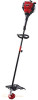
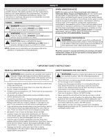
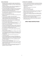
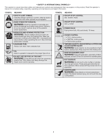
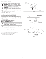
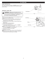
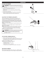
OPERATING THE COUPLER The coupler enables the use of various optional attachments. WARNING: Before using any attachment, read and understand the manual that came with the attachment. Follow all safety information contained within. WARNING: To avoid serious personal injury and damage to the unit, shut the unit off before removing or installing an attachment. NOTE: To make installing or removing the attachment easier, place the unit on the ground or on a work bench. Installing the Attachment NOTE: Remove the protective cap and gray spacer from the upper and lower shafts prior to assembling the attachment. 1. Turn the knob counterclockwise to loosen (Fig. 3). 2. While firmly holding the attachment, push it straight into the coupler until the release button snaps firmly into the primary hole (Fig. 5). NOTE: Aligning the release button with the guide recess will help installation (Fig. 4). 3. Turn the knob clockwise to tighten (Fig. 3). NOTE: Do not tighten the nut (Fig. 4). CAUTION: Before operating the unit, make sure the release button is fully snapped into the primary hole (Fig. 5) and the knob (Fig. 3) is securely tightened. CAUTION: The release button should be snapped into the primary hole only. Using the wrong hole could lead to personal injury or damage to the unit. For decorative edging with a string trimmer attachment, lock the release button into the 90° edging hole (Fig. 3). Removing the Attachment 1. Turn the knob counterclockwise to loosen (Fig. 3). 2. Press and hold the release button (Fig. 4). 3. While firmly holding the upper shaft housing, pull the attachment straight out of the coupler (Fig. 5). 90˚ Edging Hole (Trimmer Only) Coupler Fig. 3 Knob Release Button Nut Fig. 4 Primary Hole Guide Recess Upper Shaft Housing Lower Shaft Housing Fig. 5 7
-
 1
1 -
 2
2 -
 3
3 -
 4
4 -
 5
5 -
 6
6 -
 7
7 -
 8
8 -
 9
9 -
 10
10 -
 11
11 -
 12
12 -
13
-
14
-
15
-
16
-
17
-
18
-
19
-
20
-
21
-
22
-
23
-
24
-
25
-
26
-
27
-
28
-
29
-
30
-
31
-
32
-
33
-
34
-
35
-
36
-
37
-
38
-
39
-
40
 |
 |