URC KP-4000 Owners Manual
URC KP-4000 Manual
 |
View all URC KP-4000 manuals
Add to My Manuals
Save this manual to your list of manuals |
URC KP-4000 manual content summary:
- URC KP-4000 | Owners Manual - Page 1
KP-4000 Installation Manual Network Keypad - URC KP-4000 | Owners Manual - Page 2
, Inc. UNIVERSAL REMOTE CONTROL, INC. SHALL NOT BE LIABLE FOR OPERATIONAL, TECHNICAL OR EDITORIAL ERRORS/OMISSIONS MADE IN THIS MANUAL. The information in this manual may be subject to change without prior notice. Complete Control is a registered trademark of Universal Remote Control, Inc. All - URC KP-4000 | Owners Manual - Page 3
TABLE OF CONTENTS Introduction 1 Features and Benefits 2 Parts Guide 2 Network Requirements and Power Options 3 Installation Notes 5 MAC Address Labels/Reset Button 5 Connections 5 IR OUT/RFTX-1 6 12V Power 7 In-Wall Installation 8 CCP MAC Address Discovery 9 - URC KP-4000 | Owners Manual - Page 4
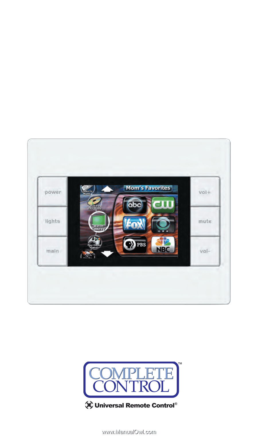
KP-4000 NETWORK KEYPAD Introduction The KP-4000 is a Network Keypad with the ability to control audio video components, energy management devices, multizone matrixes, PCs, iPods, and whole house URC Lighting. MAC addressing enables the use of multiple KP-4000's and multiple MRX-1's to control as - URC KP-4000 | Owners Manual - Page 5
new scenes whenever they like, without a PC or a programmer. They simply manually adjust each dimmer to the new setting, then press and hold a scene button or MRF-260. Parts Guide The KP-4000 Network Keypad includes: 1 - KP-4000 Network Base Station 1 - Owner's Manual 4 - Screws for mounting to a - URC KP-4000 | Owners Manual - Page 6
KP-4000 NETWORK KEYPAD Network Requirements and Power Options The KP-4000 must be connected to the same Local Area Network as the MRX-1 to function correctly. Additionally, in order for your client to enjoy internet features such as RSS feeds, the Local Area Network must be connected to the Internet - URC KP-4000 | Owners Manual - Page 7
KP-4000 NETWORK KEYPAD Option 2: PoE Injector KP-4000 PoE Injector (not included) Router 1. Connect the CAT 5 cable (RJ45) to the LAN connection on the rear of the KP-4000. 2. Plug the other end of the CAT 5 cable to the PoE Injector which will power the KP-4000. 3. Connect the PoE injector ( - URC KP-4000 | Owners Manual - Page 8
KP-4000 NETWORK KEYPAD Installation Notes MAC Address Labels/Reset Button MAC Address Label Reset Button The KP-4000 has a magnetic cover, simply pull it away from the keypad's main body to remove. Reset Button: Press this button to reset the keypad. MAC address Labels: Tear off the 2nd label - URC KP-4000 | Owners Manual - Page 9
IR OUT/RFTX-1 KP-4000 NETWORK KEYPAD This 3 Conductor removable connector can be used for either an RFTX-1 RF transmitter or for a URC IR emitter. RFTX-1 Connections In installations with URC RF lighting or a standard RF base station, you will need to add an RFTX-1 RF Transmitter to the KP-4000. - URC KP-4000 | Owners Manual - Page 10
12V Power KP-4000 NETWORK KEYPAD This 2 conductor removable connector can be used to power the KP-4000 with a wall adapter in an installation where PoE is not available. You must run an additional two conductor cable to the KP-4000 to utilize this feature. Connect a spliced power adapter 12Volt, - URC KP-4000 | Owners Manual - Page 11
KP-4000 NETWORK KEYPAD In-Wall Installation Magnetic cover plate KP-4000 Two-Gang Wall Box 1. The KP-4000 installs in a standard two gang box. If in a retrofit installation, cut in and install a standard two gang p-ring or retro fit box (not included) into the wall. 2. Make connections for IR - URC KP-4000 | Owners Manual - Page 12
KP-4000 NETWORK KEYPAD CCP MAC Address Discovery 1.Once the KP-4000 has been connected to the network, notate the MAC address located on the KP-4000 under the magnetic cover plate. 2. Open the Complete Control Program editor. 3. Select the Program tab then press Configure Home. 4. Add a KP-4000 - URC KP-4000 | Owners Manual - Page 13
KP-4000 NETWORK KEYPAD Displaying the Settings Screen You can adjust the settings of the KP-4000 whenever you like by pressing and holding both the MAIN and MUTE buttons for five seconds. When you do, the screen will change to the SETTINGS screen. If you do not press any button on the SETTINGS - URC KP-4000 | Owners Manual - Page 14
Sound KP-4000 NETWORK KEYPAD Your KP-4000 may have been programmed to make sounds. This is optional, and some professional installers may prefer to keep it silent. However, you can adjust the volume to any level you like by touching and dragging the volume control here. Adjusting Brightness - URC KP-4000 | Owners Manual - Page 15
KP-4000 NETWORK KEYPAD Factory Default WARNING! Only use this button when instructed to by Technical Support. It resets the memory of the KP-4000 to the factory condition. All your programming will be lost! Exit When you have finished adjusting Settings, - URC KP-4000 | Owners Manual - Page 16
"Yes" to reformat, and "No" to return back to the KP-4000 Settings Screen. Specifications Microprocessor: 190MHz RISC Memory: 128MB Flash Devices: Supports up to 255 Devices Pages: Supports up to 255 Pages on each Device Macro Capability: Up to 255 steps Network: One 10/100 Ethernet port (PoE) LCD - URC KP-4000 | Owners Manual - Page 17
at the address provided in the Owner's Manual. It is your responsibility to backup data, software, or other materials will be lost during service and Universal Remote Control will not be responsible for any of Purchase is required. For product support and other important information visit Universal - URC KP-4000 | Owners Manual - Page 18
installation. This equipment generates, uses and can radiate radio frequency energy and, if not installed and used in accordance with the instructions, may cause harmful interference to radio communications. However, there is no guarantee that interference will not occur in a particular installation - URC KP-4000 | Owners Manual - Page 19
MEMO Page 16 - URC KP-4000 | Owners Manual - Page 20
500 Mamaroneck Avenue, Harrison, NY 10528 Phone: (914) 835-4484 Fax: (914) 835-4532 www.universalremote.com OCE-0080A Rev.01
-
 1
1 -
 2
2 -
 3
3 -
 4
4 -
 5
5 -
 6
6 -
 7
7 -
8
-
9
-
10
-
11
-
12
-
13
-
14
-
15
-
16
-
17
-
18
-
19
-
20
 |
 |
KP-4000 Installation Manual
Network Keypad