Uniden BC235XLT English Owners Manual - Page 61
User Defined Fleet Maps, Type I Programming Information
 |
View all Uniden BC235XLT manuals
Add to My Manuals
Save this manual to your list of manuals |
Page 61 highlights
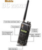
User Defined Fleet Maps Type I Programming Information When a Type I system is designed, the address information for all the IDs is divided into 8 equal sized blocks, numbered 0-7. When you program your scanner to track a Type I system, you must select a size code for each of these blocks. When you have assigned a size code to all 8 blocks, you'll have defined the Fleet Map for the system you're tracking. Each size code determines the number of Fleets, Subfleets, and IDs each block will have. For example, a size code of S-4 has one Fleet, which is divided into 16 separate Subfleets, and it has a total of 512 individual IDs. When a block is assigned a size code, the Fleet or Fleets created within the block are assigned a Type I ID. The way these IDs display on your scanner depend on the block number and the block's size code. When a Type I ID displays, the leftmost digit represents the block which contains the ID. The next two digits identify which Fleet is active, and the last digit(s) identifies the Subfleet. 4 05-12 Block (1 digit) Subfleet (1 or 2 digits) Which Fleet within the Block (2 digits) The details concerning how the size codes are selected by a Type I System designer are highly dependent on the specific needs of the system's users. Some organizations may want many subfleets with only a few radios each, while another organization may want only a few subfleets with many radios each. Your task is to program your fleet map with the same size code assignments as the trunked system. If you do this accurately, you'll track all the Fleet-Subfleet combinations used by the system. In other words, you'll hear complete communications while monitoring a trunked system. 61
-
 1
1 -
2
-
3
-
4
-
5
-
6
-
7
-
8
-
9
-
10
-
11
-
12
-
13
-
14
-
15
-
16
-
17
-
18
-
19
-
20
-
21
-
22
-
23
-
24
-
25
-
26
-
27
-
28
-
29
-
30
-
31
-
32
-
33
-
34
-
35
-
36
-
37
-
38
-
39
-
40
-
41
-
42
-
43
-
44
-
45
-
46
-
47
-
48
-
49
-
50
-
51
-
52
-
53
-
54
-
55
-
 56
56 -
 57
57 -
 58
58 -
 59
59 -
 60
60 -
 61
61 -
 62
62 -
 63
63 -
 64
64 -
 65
65 -
 66
66 -
67
-
68
-
69
 |
 |