Via ARTIGO A2000 User Manual
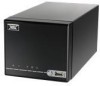
Via ARTIGO A2000 - VIA ARTiGO Barebone Storage Server Manual
 |
View all Via ARTIGO A2000 manuals
Add to My Manuals
Save this manual to your list of manuals |
Via ARTIGO A2000 manual content summary:
- Via ARTIGO A2000 | User Manual - Page 1
EPIA-N701 (ARTiGO A2000 Mainboard) USER'S MANUAL Version 1.00 December 22, 2008 - Via ARTIGO A2000 | User Manual - Page 2
form or by any means, electronic, mechanical, magnetic, optical, chemical, manual or otherwise without the prior written permission of VIA Technologies, radiate radio frequency energy and, if not installed and used in accordance with the instruction manual, may cause harmful interference to radio - Via ARTIGO A2000 | User Manual - Page 3
instructions carefully. Keep this User's Manual get the equipment checked by a service personnel: The power cord or plug is damaged. Manual. The equipment has dropped and damaged. If the equipment has obvious sign of breakage. Do not leave this equipment in an environment unconditioned or in a storage - Via ARTIGO A2000 | User Manual - Page 4
Instructions ...iii Table of Contents...iv CCChhhaaapppttteeerrr111 Specifications 1 Mainboard Specifications 2 Mainboard Layout ...4 Back Panel Layout ...5 CCChhhaaapppttteeerrr222 Installation ...7 CPU ...8 CPU Fan and System Fan: CPU_FAN and SYS_FAN 8 Memory Module Installation 9 Memory Power - Via ARTIGO A2000 | User Manual - Page 5
...33 Time...33 Video...33 Halt On ...33 SATA Drives ...34 SATA Channel 0 ...34 SATA Channel 1 ...34 Compact Flash Disk 35 Advanced BIOS Features 37 Virus Warning...37 CPU L1 & L2 Cache 37 CPU L2 Cache ECC Checking 37 Quick Power On Self-Test 38 - Via ARTIGO A2000 | User Manual - Page 6
Hole...43 System BIOS Cacheable 43 Video RAM Cacheable 43 AGP Fast Write ...43 Internal VGA Control 44 AGP 3.0 Calibration Cycle 44 VGA Share Memory Size 44 Direct Frame Buffer 44 CPU & PCI Bus Control 45 PCI Master 0 WS Write 45 PCI Delay Transaction 45 VIA PWR Management 45 Integrated - Via ARTIGO A2000 | User Manual - Page 7
50 USB Storage Function 50 Power Management Setup 51 ACPI Suspend Type 51 Power Management Option 51 HDD Power Down 51 Suspend Mode...52 Video Off Option 52 Video Off Method 52 Soft-Off by PWRBTN 52 Run VGABIOS if S3 Resume 52 AC Loss Auto Restart 52 HPET Support ...53 WDRT Support ...53 - Via ARTIGO A2000 | User Manual - Page 8
Optimized Defaults 61 Set Supervisor/User Password 62 Supervisor Password 62 User Password...62 Save & Exit Setup...64 Exit Without Saving 65 CCChhhaaapppttteeerrr555 Driver Installation 66 Driver Utilities ...67 Getting Started ...67 Running the Driver Utilities CD 68 CD Content ...69 viii - Via ARTIGO A2000 | User Manual - Page 9
exciting new generation of small, ergonomic, innovative and affordable embedded systems. Through a high level of integration, the Nano-ITX occupy 50% of the size of a MiniATX mainboard form factor. The mainboard comes with a VIA C7-D Processor, boasting of ultra-low power consumption, cool and quiet - Via ARTIGO A2000 | User Manual - Page 10
User's Manual Mainboard Specifications CPU • VIA C7-D 1.5GHz processor / 400 MHz FSB Chipset • VIA VX800 advanced all-in-one system processor Graphics • Integrated VIA Chrome9™ HC3 Integrated Graphics 3D/2D and Unified Video Decoding Accelerator Audio • VIA VT1708B High Definition Audio Codec Memory - Via ARTIGO A2000 | User Manual - Page 11
x Audio jack for Line-Out and Mic/Line-In BIOS • Award BIOS with SPI 4/8Mbit flash memory capacity Supported Operating Systems • Microsoft Windows 2000 • Microsoft Windows XP • Microsoft Windows CE • Microsoft Windows XPe • Linux based operating systems System Monitoring and Management • CPU voltage - Via ARTIGO A2000 | User Manual - Page 12
N701 User's Manual Mainboard Layout (Top View) (Bottom View) 4 - Via ARTIGO A2000 | User Manual - Page 13
N701 User's Manual Back Panel Layout 5 - Via ARTIGO A2000 | User Manual - Page 14
N701 User's Manual This page is intentionally left blank. 6 - Via ARTIGO A2000 | User Manual - Page 15
N701 User's Manual CHHAAPPTTEERR 2 INSTALLATION This chapter provides you with information about hardware installation procedures. It is recommended to use a grounded wrist strap before handling computer components. Electrostatic discharge (ESD) can damage some components. 7 - Via ARTIGO A2000 | User Manual - Page 16
N701 User's Manual CPU The VIA EPIA-N701 mainboard is packaged with a standard VIA C7-D 1.5 GHz processor. The processor requires a heatsink with fan to provide sufficient cooling. CPU Fan and System Fan: CPU_FAN and SYS_FAN The CPU_FAN (CPU fan) and SYS_FAN (System fan) run on +12V and maintain - Via ARTIGO A2000 | User Manual - Page 17
N701 User's Manual Memory Module Installation Memory Slot: DDR2 SODIMM SDRAM The VIA EPIA-N701 mainboard has one 200-pin SODIMM slot for DDR2 667/533 SDRAM memory modules and supports memory sizes up to 2GB. DDR2 SDRAM Module Installation Procedures Step 1 Locate the SODIMM slot in the mainboard. - Via ARTIGO A2000 | User Manual - Page 18
N701 User's Manual Available DDR2 SDRAM Configurations Refer to the table below for available DDR2 SDRAM configurations on the mainboard. Slot Module Size SODIMM 64MB, 128MB, 256MB, 512MB, 1GB, 2GB Maximum supported system memory Total 64MB - 2GB 2GB 10 - Via ARTIGO A2000 | User Manual - Page 19
Manual Power Connectors The VIA EPIA-N701 mainboard supports a 4-pin ATX power connector for the system power input. ATX 4-Pin Power Connector: DC 12V To connect the power supply, make sure the power the power supply connector, always make sure that all components are installed correctly to - Via ARTIGO A2000 | User Manual - Page 20
N701 User's Manual Back Panel Ports The back panel has the following ports: RJ-45 Port The board provides a standard RJ-45 (Gigabit Ethernet). This port allows the - Via ARTIGO A2000 | User Manual - Page 21
N701 User's Manual Connectors SATA Ports These next generation connectors support the thin SATA cables for primary internal storage devices. The current SATA interface allows up to 300MB/s data transfer rate, faster than the standard parallel ATA with 133 MB/s (UltraDMA). Port 2 Port 1 VGA - Via ARTIGO A2000 | User Manual - Page 22
N701 User's Manual Power Button Connector: PW_BN This pin header use to connect to the system power button. Pin Signal 1 PW_BN 2 GND 1 USB Pin Connector: USB 2/3 The mainboard provides one onboard USB pin header that enables up to two additional USB 2.0 ports. 1 - Via ARTIGO A2000 | User Manual - Page 23
N701 User's Manual KB/MS Connector The mainboard provides a PS2 pin header to and pin 8 & 10. SPI (Serial Peripheral Interface): JSPI This pin header is used to connect with SPI BIOS programming fixture. Pin Signal Pin Signal 1 SPI_VCC 2 GND 3 SPI_SS0 4 SPI_CLK 5 SPI_DI 6 SPI_DO 7 Key 8 - Via ARTIGO A2000 | User Manual - Page 24
N701 User's Manual LED Connector: JLED This pin header is for the LAN active, WLAN active, LAN speed, and HDD active LED indicators on front panel. Pin Signal 1 - Via ARTIGO A2000 | User Manual - Page 25
N701 User's Manual LPC Connector: JLPC This pin header is for LPC devices. Pin Signal Pin Signal 1 2 1 LPC_AD1 2 SIO_33_CLK 3 -PCI_RST-2 4 GND 5 LPC_AD0 6 SIO_48_CLK 7 LPC_AD2 8 -LPC_FRAME 9 SERIRQ 10 LPC_AD3 - Via ARTIGO A2000 | User Manual - Page 26
the settings of the mainboard functions using the jumpers. Clear CMOS The onboard CMOS RAM stores system configuration data and has an onboard battery power supply. To reset the CMOS settings, set the jumper on pins 1 and 2 while the system is off. Return the jumper to pins 2 and 3 afterwards - Via ARTIGO A2000 | User Manual - Page 27
N701 User's Manual Rear Audio Select: JAudio This jumper enables the pink audio jack on the back panel to switch between MIC-in and Line-in. Setting MIC-in Line-in Jumper Pairs 1&3, 2&4 3&5, 4&6 15 19 - Via ARTIGO A2000 | User Manual - Page 28
N701 User's Manual CHHAAPPTTEERR 3 DAUGHTER CARDS ARTiGO A2000 mainboard EPIA-N701 includes with two daughter cards (NSD7200-A and NSD72000-B) that support the connections to HDD SATA bay connector, front panel USB port, power button, reset button and LED indicators. This chapter shows the proper - Via ARTIGO A2000 | User Manual - Page 29
N701 User's Manual Power Cable Connection Note: The power cable for daughter card NSD7200-A must be connected to the SYS_FAN connector of the mainboard. 21 - Via ARTIGO A2000 | User Manual - Page 30
N701 User's Manual NSD7200-B Card Layout 22 - Via ARTIGO A2000 | User Manual - Page 31
N701 User's Manual Power Button Cable Connection USB Cable Connection 23 - Via ARTIGO A2000 | User Manual - Page 32
N701 User's Manual LED and Reset Cable Connection 24 - Via ARTIGO A2000 | User Manual - Page 33
N701 User's Manual This page is intentionally left blank. 25 - Via ARTIGO A2000 | User Manual - Page 34
N701 User's Manual CHHAAPPTTEERR 4 BIOS SETUP This chapter gives a detailed explanation of the BIOS setup functions. 26 - Via ARTIGO A2000 | User Manual - Page 35
N701 User's Manual Entering the BIOS Setup Menu Power on the computer and press during the beginning of the boot sequence to enter the BIOS setup menu. If you missed the BIOS setup entry point, restart the system and try again. 27 - Via ARTIGO A2000 | User Manual - Page 36
N701 User's Manual Control Keys Keys Enter Description Move to the previous item Move to the next item Move to the item in the left side Move to - Via ARTIGO A2000 | User Manual - Page 37
N701 User's Manual Navigating the BIOS Menus The main menu displays all the BIOS setup categories. Use the / and / arrow keys to select any item or sub-menu. Descriptions of the selected/highlighted category are - Via ARTIGO A2000 | User Manual - Page 38
N701 User's Manual Getting Help The BIOS setup program provides a "General Help" screen. You can display this screen from any menu/sub-menu by pressing . The help screen displays the keys for using and navigating the BIOS setup. Press to exit the help screen. 30 - Via ARTIGO A2000 | User Manual - Page 39
Features Use this menu to set chipset specific features and optimize system performance. Integrated Peripherals Use this menu to set onboard peripherals features. Power Management Setup Use this menu to set onboard power management functions. PnP/PCI Configurations Use this menu to set the PnP - Via ARTIGO A2000 | User Manual - Page 40
N701 User's Manual PC Health Status This menu shows the PC health status. Frequency/Voltage Control Use this menu to set the system frequency and voltage control. Load Optimized Defaults Use this menu option to load BIOS default settings for optimal and high performance system operations. Set - Via ARTIGO A2000 | User Manual - Page 41
N701 User's Manual Standard CMOS Features Date The date format is [Day, Month Date, Year] Time The time format is [Hour : Minute : Second] Video Settings: [EGA/VGA, CGA 40, CGA 80, MONO] Halt On Set the system's response to specific boot errors. Below is a table that details the possible - Via ARTIGO A2000 | User Manual - Page 42
N701 User's Manual SATA Drives SATA Channel 0 SATA Channel 1 34 - Via ARTIGO A2000 | User Manual - Page 43
N701 User's Manual Compact Flash Disk 35 - Via ARTIGO A2000 | User Manual - Page 44
Sector Description The name of this match the name of the menu. Settings: [None, Auto, Manual] Settings: [None, Auto, Manual] Settings: [CHS, LBA, Large, Auto] Formatted size of the storage device Number of cylinders Number of heads Write precompensation Cylinder location of the landing zone Number - Via ARTIGO A2000 | User Manual - Page 45
N701 User's Manual Advanced BIOS Features Virus Warning Allows you to choose the VIRUS warning virus protection Note: If this function is enabled and someone attempt to write data into this area, BIOS will show a warning message on the screen and alarm beep. CPU L1 & L2 Cache Settings Disabled - Via ARTIGO A2000 | User Manual - Page 46
to enable shorter boot up time. Settings Disabled Enabled Description Standard Power On Self Test (POST) Shorten Power On Self Test (POST) cycle and boot up time First/Second/Third Boot Device Set the boot device sequence as BIOS attempts to load the disk operating system. Settings LS120 Hard - Via ARTIGO A2000 | User Manual - Page 47
N701 User's Manual Typematic Rate (Chars/ BIOS Setup System Password prompt appears every time when the computer is powered on and when end users try to run BIOS Settings: [Disabled, Enabled] Video BIOS Shadow Enabled copies Video BIOS to shadow RAM Improves performance. Settings: [Disabled, - Via ARTIGO A2000 | User Manual - Page 48
N701 User's Manual Summary Screen Show Show summary screen. Settings: [Disabled, Enabled] 40 - Via ARTIGO A2000 | User Manual - Page 49
N701 User's Manual CPU Features Delay Prior to Thermal Settings: [4 Min, 8 Min, 16 Min, 32 Min] Thermal Management This item sets CPU's thermal control rule to protect CPU from overheat. Settings Thermal Monitor 1 Thermal Monitor 2 Description On-die throtting Ratio & VID transition 41 - Via ARTIGO A2000 | User Manual - Page 50
N701 User's Manual Hard Disk Boot Priority This is for setting the priority of the hard disk boot order when the "Hard Disk" option is selected in the "[First/Second/Third] Boot Device" menu item. 42 - Via ARTIGO A2000 | User Manual - Page 51
's Manual Advanced Chipset Features Caution: The Advanced Chipset Features menu is used for optimizing the chipset functions. Do not change these settings unless you are familiar with the chipset. Memory Hole Settings: [Disabled, 15M - 16M] System BIOS Cacheable Settings: [Disabled, Enabled] Video - Via ARTIGO A2000 | User Manual - Page 52
N701 User's Manual Internal VGA Control AGP 3.0 Calibration Cycle Settings: [Disabled, Enabled] VGA Share Memory Size This setting allows you to select the amount of system memory that is allocated to the integrated graphics processor. Settings: [Disabled, 64M, 128M, 256M] Direct Frame Buffer - Via ARTIGO A2000 | User Manual - Page 53
N701 User's Manual CPU & PCI Bus Control PCI Master 0 WS Write Settings: [Enabled, Disabled] PCI Delay Transaction Settings: [Disabled, Enabled] VIA PWR Management Settings: [Disabled, Enabled] 45 - Via ARTIGO A2000 | User Manual - Page 54
Manual Integrated Peripherals OnChip IDE Channel 1 Settings: [Disabled, Enabled] IDE HDD Block Mode Settings: [Disabled, Enabled] SATA Controller Settings: [Disabled, Enabled] Azalia HDA Controller Settings: [Auto, Disabled] Onboard LAN Boot ROM Settings: [Enabled, Disabled] VIA Wireless LAN Support - Via ARTIGO A2000 | User Manual - Page 55
N701 User's Manual Super IO Device Internal Serial Port 1 Settings: [Disabled, 3F8/IRQ4, 2F8/IRQ3, 3E8/IRQ4, 2E8/IRQ3] 47 - Via ARTIGO A2000 | User Manual - Page 56
N701 User's Manual VIA OnChip IDE Device IDE Prefetch Mode Settings: [Disabled, Enabled] CF Card UDMA66 Settings: [Disabled, Enabled] IDE DMA Transfer Access Settings: [Disabled, Enabled] Compact Flash PIO - Via ARTIGO A2000 | User Manual - Page 57
N701 User's Manual USB Device Setting USB 1.0 Controller Enable or disable Universal Host Controller Interface for Universal Serial Bus. Settings: device, then it operated on high speed mode. USB Keyboard Function Enable or disable Legacy support of USB Keyboard. Settings: [Disabled, Enabled] 49 - Via ARTIGO A2000 | User Manual - Page 58
N701 User's Manual USB Mouse Function Settings: [Disabled, Enabled] USB Storage Function Enable or disable Legacy support of USB Mass Storage. Settings: [Disabled, Enabled] 50 - Via ARTIGO A2000 | User Manual - Page 59
contexts. S3/Suspend To RAM (STR) is a power-down state. In this state, power is supplied only to essential components such as main memory and wakeup-capable devices. The system context is saved to main memory, and context is restored from the memory when a "wakeup" event occurs. Depends on the - Via ARTIGO A2000 | User Manual - Page 60
OS such as Windows XP will override this option. Settings Always On Suspend -> Off Description Screen is always on even when system enters power saving mode Screen is turned off when system enters power saving mode Video Off Method Settings: [Blank Screen, V/H SYNC+Blank, DPMS Support] Soft-Off - Via ARTIGO A2000 | User Manual - Page 61
N701 User's Manual HPET Support Settings: [Disabled, Enabled] WDRT Support Settings: [Disabled, Enabled] 53 - Via ARTIGO A2000 | User Manual - Page 62
N701 User's Manual Wakeup Event Detect PS2KB Wakeup Select When selecting "Password", press - Via ARTIGO A2000 | User Manual - Page 63
N701 User's Manual PS2 Mouse Power On Settings: [Disabled, Enabled] USB Resume from S3 Settings: [Disabled, Enabled] Wakeup On GPI Settings: [Disabled, Enabled] PowerOn by PCI Card Enables activity detected from any PCI card to power up the system or resume from a suspended state. Such PCI cards - Via ARTIGO A2000 | User Manual - Page 64
N701 User's Manual PnP/PCI Configurations Note: This section covers some very technical items and it is strongly recommended to leave the default settings as is unless you are an experienced user. PNP OS Installed Settings No Yes Description BIOS will initialize all the PnP cards BIOS will only - Via ARTIGO A2000 | User Manual - Page 65
to automatically configure all the Plug-and-Play compatible devices. Settings Auto(ESCD) Manual Description BIOS will automatically assign IRQ, DMA and memory base address fields Unlocks "IRQ Resources" for manual configuration PCI/VGA Palette Snoop Some non-standard VGA display cards may not - Via ARTIGO A2000 | User Manual - Page 66
N701 User's Manual PC Health Status The PC Health Status displays the current status of all of the monitored hardware devices/components such as CPU voltages, temperatures and fan speeds. 58 - Via ARTIGO A2000 | User Manual - Page 67
N701 User's Manual Frequency/Voltage Control DRAM Frequency Settings: [DDR2-400, DDR2-533, DDR-667, SPD] DRAM Channel Mode Settings: [Channel A, Channel A&B, Channel A&C] DDR CAS Latency Control Settings: [ - Via ARTIGO A2000 | User Manual - Page 68
N701 User's Manual Spread Spectrum When the mainboard's clock generator pulses, the extreme values (spikes) of the pulses create EMI (Electromagnetic Interference). The Spread Spectrum function reduces the - Via ARTIGO A2000 | User Manual - Page 69
's Manual Load Optimized Defaults This option is for restoring all the default optimized BIOS settings. The default optimized values are set by the mainboard manufacturer to provide a stable system with optimized performance. Entering "Y" and press to load the default optimized BIOS values - Via ARTIGO A2000 | User Manual - Page 70
N701 User's Manual Set Supervisor/User Password Supervisor Password User Password This option is for setting a password for entering BIOS Setup. When a password has been set, a password prompt will be displayed whenever BIOS Setup is run. This prevents an unauthorized person from changing any part - Via ARTIGO A2000 | User Manual - Page 71
Manual There are two types of passwords you can set. A supervisor password and a user password. When a supervisor password is used, the BIOS Setup program can be accessed and the BIOS settings can be changed. When a user password is used, the BIOS Setup program can be accessed but the BIOS settings - Via ARTIGO A2000 | User Manual - Page 72
N701 User's Manual Save & Exit Setup Entering "Y" saves any changes made, and exits the program. Entering "N" will cancel the exit request. 64 - Via ARTIGO A2000 | User Manual - Page 73
N701 User's Manual Exit Without Saving Entering "Y' discards any changes made and exits the program. Entering "N" will cancel the exit request. 65 - Via ARTIGO A2000 | User Manual - Page 74
's Manual CHHAAPPTTEERR 5 DRIVER INSTALLATION This chapter gives you brief descriptions of each mainboard driver and application. You must install the VIA chipset drivers first before installing other drivers such as VGA drivers. The applications will only function correctly if the necessary drivers - Via ARTIGO A2000 | User Manual - Page 75
N701 User's Manual Driver Utilities Getting Started The mainboard includes a Driver Utilities CD that contains the drivers and software for enhancing the performance of the mainboard. If the CD is missing from the retail box, please contact the local dealer for the CD. Note: The driver utilities and - Via ARTIGO A2000 | User Manual - Page 76
Manual Running the Driver Utilities CD To start using the CD, insert the CD into the CD-ROM or DVD-ROM drive. The CD should run automatically after closing the CD-ROM or DVD-ROM drive. The driver Linux drivers, click the right button on mouse and click open. Linux drivers are located in the "Driver" - Via ARTIGO A2000 | User Manual - Page 77
N701 User's Manual CD Content VIA 4in1 Drivers: Contains VIA ATAPI Vendor Support Driver (enables the performance enhancing bus mastering functions on ATAcapable Hard Disk Drives and ensures IDE device compatibility), AGP VxD Driver (provides service routines to your VGA driver and interface
-
 1
1 -
 2
2 -
 3
3 -
 4
4 -
 5
5 -
 6
6 -
 7
7 -
8
-
9
-
10
-
11
-
12
-
13
-
14
-
15
-
16
-
17
-
18
-
19
-
20
-
21
-
22
-
23
-
24
-
25
-
26
-
27
-
28
-
29
-
30
-
31
-
32
-
33
-
34
-
35
-
36
-
37
-
38
-
39
-
40
-
41
-
42
-
43
-
44
-
45
-
46
-
47
-
48
-
49
-
50
-
51
-
52
-
53
-
54
-
55
-
56
-
57
-
58
-
59
-
60
-
61
-
62
-
63
-
64
-
65
-
66
-
67
-
68
-
69
-
70
-
71
-
72
-
73
-
74
-
75
-
76
-
77
 |
 |

EPIA
EPIA
EPIA
EPIA-N701
N701
N701
N701
(ARTiGO A2000 Mainboard)
U
SER
SER
SER
SER
’
S
S
S
S
M
ANUAL
ANUAL
ANUAL
ANUAL
Version 1.00
December 22, 2008