ViewSonic N2635W User Guide - Page 20
Rear View of the Product - no power
 |
UPC - 766907265316
View all ViewSonic N2635W manuals
Add to My Manuals
Save this manual to your list of manuals |
Page 20 highlights
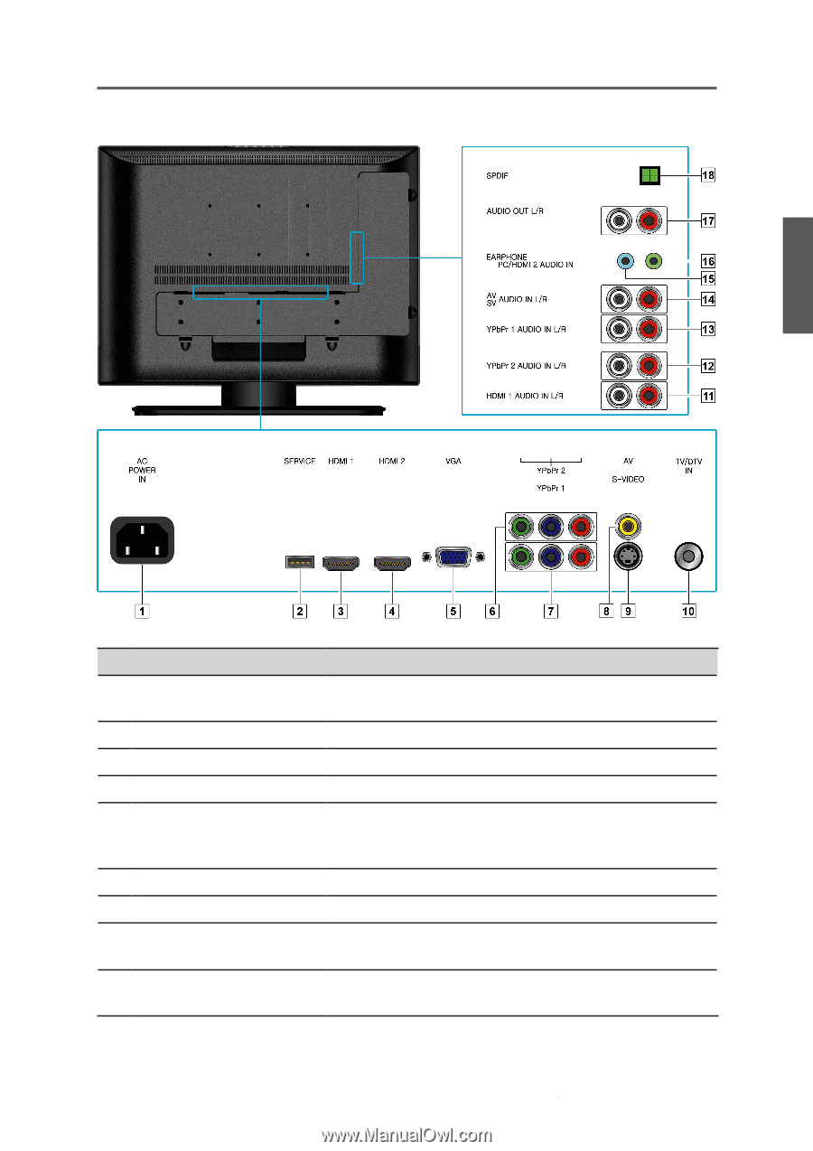
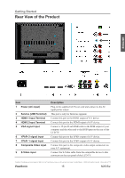
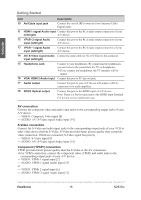
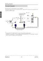
Getting Started Rear View of the Product ENGLISH Item 1 Power (AC input) 2 Service (USB Terminal) 3 HDMI 1 Input Terminal 4 HDMI 2 Input Terminal 5 VGA signal input 6 YPbPr 2 signal input 7 YPbPr 1 signal input 8 Composite Video input 9 S-Video input Description Plug-in the supplied AC Power cord and connect to the AC input power source. This port is only for firmware upgrade. Connect this port to the HDMI output of A/V device. Connect this port to the HDMI output of A/V device. Connect a 15-pin D-sub RGB cable to the RGB output of your computer and the other end to the RGB input on the rear of the LCD TV. Connect this port to the YPbPr output of A/V device. Connect this port to the YPbPr output of A/V device. Connect this jack to the composite video output connectors on your A/V equipment. Connect the S-Video cable from the compatible device to this connector on the rear panel of the LCD TV. Contact ViewSonic service team at: http://www.ViewSonic.com or call our service team: United States 1-800-688-6688, Canada 1-866-463-4775 ViewSonic 15 N2635w
-
 1
1 -
2
-
3
-
4
-
5
-
6
-
7
-
8
-
9
-
10
-
11
-
12
-
13
-
14
-
 15
15 -
 16
16 -
 17
17 -
 18
18 -
 19
19 -
 20
20 -
 21
21 -
 22
22 -
 23
23 -
 24
24 -
 25
25 -
26
-
27
-
28
-
29
-
30
-
31
-
32
-
33
-
34
-
35
-
36
-
37
-
38
-
39
-
40
-
41
-
42
-
43
-
44
-
45
-
46
-
47
-
48
-
49
-
50
 |
 |