ViewSonic PJ-WMK-305 Quick Start Guide
ViewSonic PJ-WMK-305 Manual
 |
View all ViewSonic PJ-WMK-305 manuals
Add to My Manuals
Save this manual to your list of manuals |
ViewSonic PJ-WMK-305 manual content summary:
- ViewSonic PJ-WMK-305 | Quick Start Guide - Page 1
PJ-WMK-305 Quick Start Guide Checking The Supplied Accessories Fixing Kit Projector Mounting Fixed Support Arm x1 Plate x 1 Wall Plate x 1 Wall Cover x 1 Important Safety Informa�on 1. Please read this manual carefully and follow all safety rules before installa�on. 2. For safety reasons,
-
 1
1
 |
 |
PJ-WMK-305
Quick Start Guide
中国
电话:
4008 988 188
香港
電話:
852 3102 2900
澳門
電話:
853 2833 8407
台灣
電話:
0800 899 880
한국
Phone: 080 333 2131
Singapore/Malaysia/Thailand
Phone: 65 6461 6044
India
Phone: 1800-419-0959
United States
Phone: 1-800-688-6688
Canada
Phone: 1-866-463-4775
Europe
Australia/New Zealand
Phone: 1800 880 818 (AUS)
0800 008 822 (NZ)
South Africa
Latin America (Chile)
Latin America (Mexico)
Latin America (Peru)
Latin America (Argentina)
Puerto Rico & Virgin Islands
Phone: 1-800-688-6688 (English)
PJ-WMK-305_QSG_Rev. 1a 01-14-21
Copyright © 2021 ViewSonic Corporation. All rights reserved.
Checking The Supplied Accessories
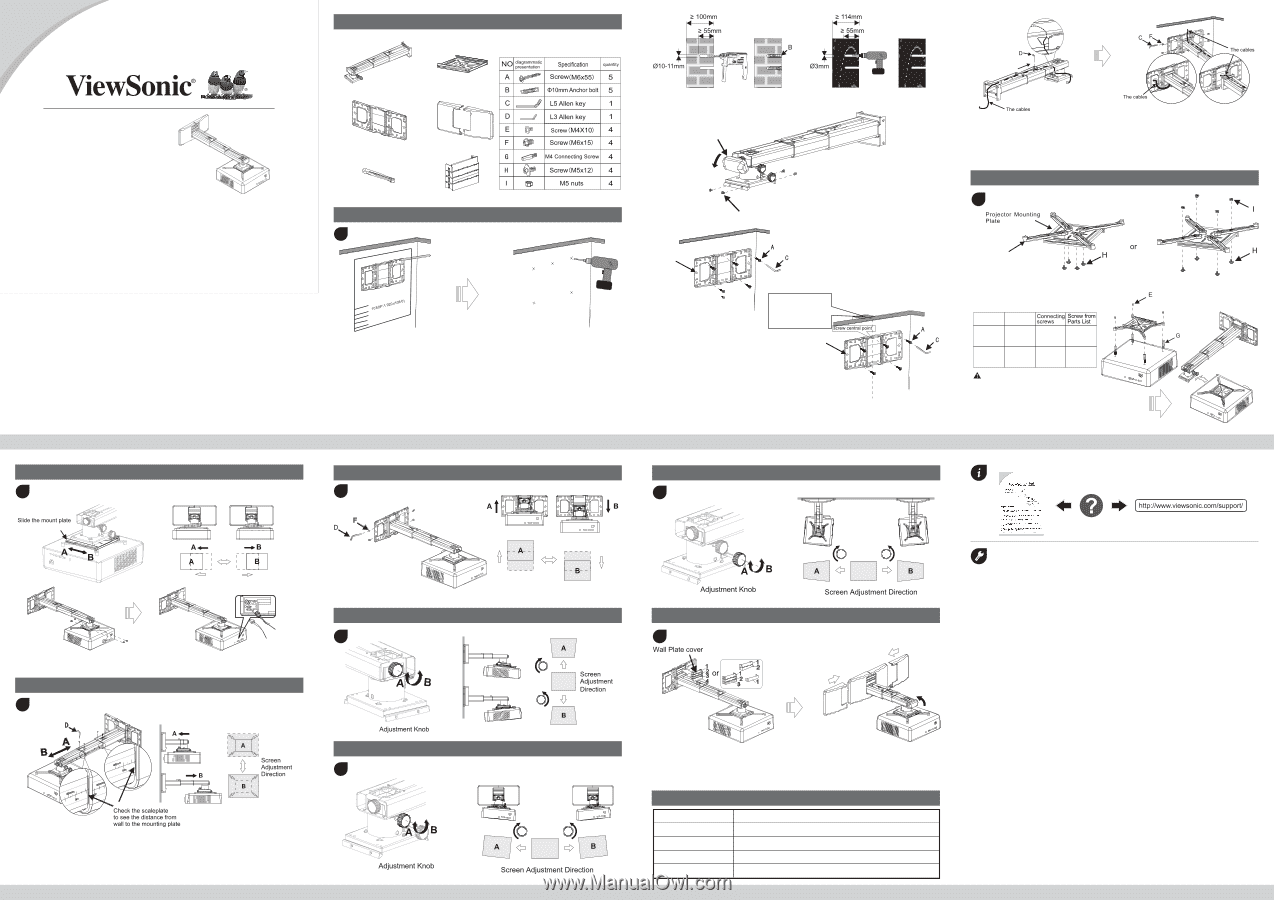
Setting The Projector Wall Mount On The Wall
• If the board has been installed, please align the center line of the projector lens on the
installation chart with that of the screen or board to the locate the place of the mount period.
• For concrete wall mounting, thickness of the wall must be not less than 4'' (100mm). Anchor
bolt and screw (M6x55) are needed
to be used for concrete wall installation.
• For Dry-wall mounting, thickness of the dry-wall must be not less than 4.5" (114mm). Only
screw (M6x55) is needed to be
used for installation, and gypsum board thickness less than
0.59" (15mm).
Note
: If the thickness of wall is not strong enough, reinforce it sufficiently before installation.
Note:
To make adjustments to meet your demands, screws must be loosened in a
specific order, as shown in the above figure. (When the length of inside arm
895mm do not meet your demands, then you should loose the screws on the
outside arm to adjust the middle arm. Under this circumstance, the number
read on the middle arm is correct).
Adjusting The Image Height
Adjusting The Horizontal Rotation
Adjusting The Vertical Tilt
Placing The Decorative Cover
Note:
When all adjustments are done, the wall plate covers can be used to cover the
blank area on the top of wall plate. The number of wall plate cover used
depends on the size of blank area. But
the wall cover must be used in an
specific order as the picture on left shows. Finally, put the wall cover on.
1
2
3
4
6
5
8
9
Adjusting The Horizontal Roll
7
Fixed Support Arm x1
Projector Mounting
Plate x 1
Wall Plate x 1
Wall Cover x 1
Projector Mounting
Arms x4
Wall Plate Cover x 1
Concrete wall mounting
take off the cover
loosen the screw
• Insert Screw A (M6x55) from the fixing kit, tighten with a L5 Allen Key from fixing kit.
a. Use the extend arm
b. Install the Projector Mounting Plate to the Projector
• Insert Screw F(M6x15) from the fixing kit, tighten with a L5 Allen Key from fixing kit.
Dry-wall mounting
With anchor bolt
Without anchor bolt
Installing The Projector On The Projector Wall Mount
Screen Adjustment Direction
Adjusting The image horizontally
Adjusting The Image Size
Fixing Kit
The arrows up
The arrows up
When installation on the
wood stud wall, Align the
center of the wall mount
plate with the center of
the stud.
Loosen the screws with L3 allen wrench,
pull out the support arm around
4''
(100mm)and make power cable & signal
cables go through the support arm.
The cables can go through the wall plate
by three ways as shown in the pictures.
Then, tighten the screw
F
after locating
the projector position.
Screen Adjustment Direction
Connect power cable and other signal cable to the projector
Tighten the screws
Power cable
Signal cable
Product Information
15 lb (6.8 kg)
PJ-WMK-305
Model
Net Weight
Weight Capacity
Extendable Length
Adjustment Angle
22 lb (10.0 kg)
19"-49" (495-1250mm)
Vertical tilt, Horizontal roll, Horizontal rotation ±5°
Important Safety Informa�on
1.
Please read this manual carefully and follow all safety rules before installa�on.
2. For safety reasons, please make sure the wall is strong enough to sustain the weight of the
projector & wall mount.
3. The total maximum weight of all items mounted should NEVER exceed the weight capacity: 55 lbs
(25kg).
4.
DO NOT a±empt to alter or modify any part of the wall mount or its a±achments.
5.
Do not install the projector wall mount on a structure that is prone to vibra�on, movement or
chance of impact.
6.
To avoid risk of fire, do not install the projector with the projector wall mount in a humid or
excessively dusty place.
7. Use the supplied accessories only. Use of accessories other than those supplied may result in
damage to the projector and/or projector wall mount.
8. Unplug the AC power cord and any other connected cables before dismounting the projector from
the projector wall mount.
9. Do not hit or hang any heavy objects on the projector wall mount. If the projector wall mount is
damaged, stop using immediately and contact a qualified service personnel immediately.
10. Only install the projector wall mount horizontally on the level surfaces.
* The manufacturer is not liable for any damages or injury caused by mishandling or improper
installa�on.
11. The projector or wall mount may fall and cause personal injury. Ensure screws are tightened to the
proper torque after installation and any adjustments. Do not overtighten screws as this may cause
screw deformation.
12. This wall mount kit ONLY supports ViewSonic® projectors and models that are designated by
ViewSonic. Use with non-ViewSonic branded projectors or exceeding the weight capacity is
neither supported nor recommended, may cause property damage or personal injury, and shall be
at the sole risk of users/installers.
E (M4x10)
E (M4x10)
Use
Connecting
screws G
M4
M4
Bulging
Flat
Screw E & G Tightening torque:
8kgf-cm (
≦
12kgf-cm)
Screw hole
on projector
Screw hole
on projector
Extend Arm
No need
Connecting
screw G