ViewSonic VG150B Service Manual
ViewSonic VG150B - 15" LCD Monitor Manual
 |
View all ViewSonic VG150B manuals
Add to My Manuals
Save this manual to your list of manuals |
ViewSonic VG150B manual content summary:
- ViewSonic VG150B | Service Manual - Page 1
Service Manual ViewSonic VG150 ViewPaner Model No. VLCDS21457-1 15" Active Matrix LCD Color Monitor ViewSonic® IMIviedill -161 (Rev. 1 - April 1999) ViewSonic® 381 Brea Canyon Road, Walnut, California 91789 USA - (800) 888-8583 - ViewSonic VG150B | Service Manual - Page 2
. Trademarks ViewSonic is a registered trademark of ViewSonic Corporation. All other trademarks used within this document are the property of their respective owners. Revision History Revision Date Description Of Changes 1.0 4/29/99 Initial Issue Approval T. Sears ii VG150 Service Manual - ViewSonic VG150B | Service Manual - Page 3
TABLE OF CONTENTS PRECAUTIONS AND SAFETY WARNINGS FEATURES SPECIFICATIONS BLOCK DIAGRAMS MAIN BOARD I/O CONNECTIONS THEORY OF CIRCUIT OPERATION WAVEFORMS TROUBLESHOOTING SPARE PARTS LIST COMPLETE PARTS LIST SCHEMATIC DRAWING 1 2 3-6 7 8-11 12-30 31-38 39-41 42 43-58 59 iii VG150 Service Manual - ViewSonic VG150B | Service Manual - Page 4
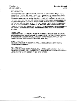
ViewSonic April 1999 - Version 1.0 Service Manual VG150 FCC INFORMATION This equipment has been tested and found to comply with the limits of a Class B digital device, pursuant to part 15 user must use a grounded power supply cord power cable that is properly grounded. Always use the AC cords as - ViewSonic VG150B | Service Manual - Page 5
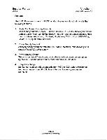
Manual VG150 ViewSon ic April 1999 - Version 1.0 Features The VG150 are world class TFT LCD analog display monitors that include the following features. 1. Digital On Screen Display Controls User friendly buttons (Power, Function, Select (+ / -), Auto) allowing for picture perfect quality. User - ViewSonic VG150B | Service Manual - Page 6
ViewSonic April 1999 - Version 1.0 SPECIFICATIONS Service Manual VG150 Characteristic LCD Panel Maximum Viewing Angles Signal Input Connector Maximum Resolution Video Bandwidth Display Area Power Voltage Power Consumption Operating Conditions Storage Conditions Dimensions Weight Description ADI, - ViewSonic VG150B | Service Manual - Page 7
Service Manual VG150 ON SCREEN DISPLAY ViewSonic April 1999 - Version 1.0 OSD (On Screen Display) function is supported on each the TFT LCD analog display monitors and is controlled by four easy to use buttons - Power, Function, Select (+), Select (-), Auto. Function Auto Sync Contrast Brightness - ViewSonic VG150B | Service Manual - Page 8
ViewSonic April 1999 - Version 1.0 FACTORY PRESET TIMINGS Service Manual VG150 This timing chart is already preset for the TFT LCD analog display monitors kHz - 31.46 + 31.46 - 31.47 - 37.86 - 37.50 - 35.00 - 35.15 + 37.87 + 48.07 + 46.87 + 48.36 - 56.47 - 58.03 - 60.02 - ViewSonic VG150B | Service Manual - Page 9
Service Manual VG150 PIN ASSIGNMENT ViewSonic April 1999 - Version 1.0 The TFT LCD analog display monitors use a 15 Pin Mini D-Sub connector as video input source. Pin Description 1 Red 2 Green 3 Blue 4 Ground 5 Ground 6 R-Ground 7 G-Ground 8 B-Ground 9 No Connection 10 Ground 11 No Connection - ViewSonic VG150B | Service Manual - Page 10
ViewSonic April 1999 - Version 1.0 BLOCK DIAGRAM Service Manual VG150 COMPLETE TFT LCD DISPLAY UNIT AC Outlet Video Card Adaptor Analog Signal 12V H Inverter • Brightness Control • 12V► Main Board 700Vac Digital TFT Signal". LCD Panel MAIN BOARD (TFT LCD DISPLAY ANALOG INTERFACE CONTROL - ViewSonic VG150B | Service Manual - Page 11
Service Manual VG150 MAIN BOARD I/O CONNECTIONS W04 CONNECTION (LEFTORIGHT) "OSD CONTROL" Pin Description 1 "-" Key 2 " Function " Key 3 "+" Key 4 Recall 5 LED 1 6 LED 2 7 Ground 8 Power 1 9 Power 2 W05 CONNECTION (TOPOBOTTOM) "INVERTER CONTROL" Pin Description 1 +12V 2 Ground 3 V - ViewSonic VG150B | Service Manual - Page 12
ViewSonic April 1999 - Version 1.0 MAIN BOARD I/O CONNECTIONS Service Manual VG150 W07 CONNECTION "VIDEO SIGNAL OUT To LCD PANEL" Pin Description 1 N.C. 2 N.C. 3 N.C. 4 N.C. 5 N.C. 6 N.C. 7 Red Odd Data Signal (LSB) 8 Ground 9 Red Odd Data Signal 10 Red Odd Data Signal 11 Red Odd Data Signal 12 - ViewSonic VG150B | Service Manual - Page 13
Service Manual VG150 MAIN BOARD I/O CONNECTIONS W07 CONNECTION "VIDEO SIGNAL OUT To LCD PANEL" ViewSonic April 1999 - Version 1.0 Pin Description 61 Ground 62 Ground 63 V Sync Signal 64 Ground 65 Data Enable Signal 66 H Sync Signal 67 Ground 68 Ground - ViewSonic VG150B | Service Manual - Page 14
ViewSonic April 1999 - Version 1.0 INVERTER BOARD I/O CONNECTIONS Service Manual VG150 V-out GND V-control ON/OFF GND 12V TDK V-out GND NOTE: MANUFACTURER'S NAME MUST BE ON THE PRINTED SIDE FOR THE INVERTER BOARD TO BE FACING UP. ronfideifPfiaaTg1e151-1NiiiCiffi2 - ViewSonic VG150B | Service Manual - Page 15
Service Manual VG150 THEORY OF CIRCUIT OPERATION ViewSonic April 1999 - Version 1.0 The VG150 are multi-frequency and multi-mode color TFT LCD monitors. It supports true XGA resolution of 1024x768 including SVGA, VGA and other various high resolution modes up to 1024x768 for IBM, PC compatibles, - ViewSonic VG150B | Service Manual - Page 16
ViewSonic April 1999 - Version 1.0 THEORY OF CIRCUIT OPERATION Service Manual VG150 412 1,41.0 III S11 the Schematic on page 59. This product uses 74HC4053 as a signal switch in order to support Composite SYNC . If the input signal is out of specification or interrupted, the free run mode will - ViewSonic VG150B | Service Manual - Page 17
Service Manual VG150 THEORY OF CIRCUIT OPERATION ViewSonic April 1999 - Version 1.0 This product supports timing from VGA to XGA, so the pixel rate is from 25 MHz to 80 MHz. In order to make the phases of sampling clock and video to be closed to each other easily and precisely when user Upon power - ViewSonic VG150B | Service Manual - Page 18
version of this drawing, refer to the Schematic on page 59. AM30 is a triple 8-bits AID converter optimized for XGA LCD monitor with maximum sample rate of 96 MSPS. It can support both single-channel and dualchannel digital outputs. The analog input range of AM30 is (0.6V - 2.6 V). The external top - ViewSonic VG150B | Service Manual - Page 19
Service Manual VG150 ViewSonic April 1999 - Version 1.0 THEORY OF CIRCUIT OPERATION AM100 The AM100 is capable of performing automatic detection of the display resolution and timing of the input signals generated from various graphic cards. The AM100 then automatically scales the input image to - ViewSonic VG150B | Service Manual - Page 20
ViewSonic April 1999 - Version 1.0 THEORY OF CIRCUIT OPERATION Service Manual VG150 Image Scaling The AM100 supports several different input modes, and the input image may have different sizes. It is essential to support automatic image scaling so that the input image is always displayed to the - ViewSonic VG150B | Service Manual - Page 21
Service Manual VG150 ViewSonic April 1999 - Version 1.0 THEORY OF CIRCUIT OPERATION OSD mixer In the EN_OSD is active high, the OSD is active, and the AM100 will send the OSD data to the LCD panel. The OSD has 16 different color schemes based on the combinations of the three OSD color pins and the - ViewSonic VG150B | Service Manual - Page 22
ViewSonic April 1999 - Version 1.0 THEORY OF CIRCUIT OPERATION Service Manual VG150 Symbol HBP W 640 640 720 640 800 1024 Description x x x x x x 350 400 400 480 600 768 11 OCH 2CH 4CH 6CH 8CH ACH LCD 1 1: 2 to 3 2: 3 to 4 3: 5 to 8 4: 15 to 32 5: 25 to 32 6: 25 to 48 7: 25 to 64 - ViewSonic VG150B | Service Manual - Page 23
Service Manual VG150 THEORY OF CIRCUIT OPERATION ViewSonic April 1999 - Version 1.0 Symbol W Fog Factor 8 Vertical Minimum 11 input lines Maximum 11 Input pixels Source 3 HSIZE[11:8] Source 3 HSIZE[11:8] Source 8 HSIZE[7:0] Source 8 VSIZE[7:0] - ViewSonic VG150B | Service Manual - Page 24
ViewSonic April 1999 - Version 1.0 THEORY OF CIRCUIT OPERATION Service Manual VG150 Input Mode Detection Data Symbol Calibration mode ResO threshold Res1 threshold Res2 threshold Res3 threshold Res4 threshold Res5 threshold Res6 threshold Mode 640x350 Sync Polarity - ViewSonic VG150B | Service Manual - Page 25
Service Manual VG150 THEORY OF CIRCUIT OPERATION ViewSonic April 1999 - Version 1.0 Symbol Mode ,000 us / lus = 1,000,000 is used here. 13Ah-13BH 13CH 13DH Maximum refresh rate supported by the LCD panel If the intended maximum refresh rate is 75Hz, and the free-running clock is 1MHz, then a - ViewSonic VG150B | Service Manual - Page 26
ViewSonic April 1999 - Version 1.0 THEORY OF CIRCUIT OPERATION Service Manual VG150 Symbol Width (bits) Offset factor CE 8 Offset factor CO 8 Offset factor NE 8 Offset factor NO 8 Scale factor V 8 Minimum pixels per 11 line for LCD LCD per line for LCD panel Controls the polarity of - ViewSonic VG150B | Service Manual - Page 27
Service Manual VG150 THEORY OF CIRCUIT OPERATION ViewSonic April 1999 - Version 1.0 The MTV112E micro controller is an 8051CPU core embedded device specially tailored to CRT monitor applications. It includes an 8051 CPU core, 256 bytes SRAM, fourteen built-in PWM DACs, DDC1/DDC2B interface, 24Cxx - ViewSonic VG150B | Service Manual - Page 28
ViewSonic April 1999 - Version 1.0 THEORY OF CIRCUIT OPERATION Service Manual VG150 The MTV112E pin functions are list below PIN# 1 2 3 4 5 6 7 8 9 10 11 12 Name P1.0 P1.1 P1.2 P1.3 P1.4 P1.5 P1.6/ADD P1.7/AD1 RST HSCL HSDA ISDA 13 HSYNC 14 ISCL 15 input - Negative Power Supply - Reserve I/O - ViewSonic VG150B | Service Manual - Page 29
Service Manual VG150 THEORY OF CIRCUIT OPERATION ViewSonic April 1999 - Version 1.0 PIN# 26 27 28 29 30 31 32 33 34 35 O Sync on green /separate or composite select O V-Sync select (VBK/external V-Sync) O Free run mode enable O Power of inverter on/off control - Positive Power Supply Page 26 - ViewSonic VG150B | Service Manual - Page 30
ViewSonic April 1999 - Version 1.0 THEORY OF CIRCUIT OPERATION HN SYNC Processing Service Manual VG150 VSYNC HSYNC Digital Filter separate The MTV112E continuously monitors the input HSYNC, if the vertical sync pulse can be extracted from the input, a CVpre flag is set and user can select the - ViewSonic VG150B | Service Manual - Page 31
Service Manual VG150 THEORY OF CIRCUIT OPERATION ViewSonic April 1999 - Version 1.0 HN Frequency Counter MT1/112E can discriminate HSYNCNSYNC frequency and saves the information in XFRs. The 15 bits Hcounter counts the time of 64XHSYNC period, but only 11 upper bits are loaded into the HCNTH/HCNTL - ViewSonic VG150B | Service Manual - Page 32
ViewSonic April 1999 - Version 1.0 THEORY OF CIRCUIT OPERATION Service Manual VG150 for line-locked and gen-locked high resolution video applications. It offers pixel clock detector (PFD). The Oscillator frequency range of VCO is set by an panel. Page 29 troKflifiriffirThicNo-T--C---e--i-ii-9 - ViewSonic VG150B | Service Manual - Page 33
Service Manual VG150 THEORY OF CIRCUIT OPERATION ViewSonic April 1999 - Version 1.0 POWER SYSTEM 1442 32 021022. 012 47. C103 .122 2032 102 2.02102222. O .61/14 0112 22.2 1 • • 47• 22 1C13 1.7304 42 R7 2. 13 02 7 1 + 0713 330u - R. - ViewSonic VG150B | Service Manual - Page 34
ViewSonic April 1999 - Version 1.0 WAVEFORMS H-SYNC SIGNAL (1C25 AT PIN 3) Tek IMRE 10 s/s 1554 Acqs a. .. . M "51:ta V-SYNC SIGNAL (IC25 AT PIN 5) talc RIEBEIES 58S/ 8 I ;I 5 Acqs Service Manual VG150 Imms Ch1 Period 16.7j.ts aChU1 ZI -1-1•4-+ vv-arlyre" .`s' 31 Mar 1999 15:27:59 .: 3.6ms - ViewSonic VG150B | Service Manual - Page 35
Service Manual VG150 WAVEFORMS SERIAL DATA (IC24 AT PIN 5) iek 2 MSfs ... 64 Acqs ViewSonic April 1999 - Version 1.0 es: 8.5µS C0: -86ms ps-rsesr''' 31 Mar 1999 15:43:10 PWM BRIGHTNESS CONTROL (IC25 AT PIN 39) RIXESES 71,15/s 63 Acqs 8.5yas 01: -86MS . 11/1 25µs PRE-AMP R-OUT (IC31 AT PIN - ViewSonic VG150B | Service Manual - Page 36
ViewSonic April 1999 - Version 1.0 WAVEFORMS A/D DATA OUTPUT BIT 7 (IC08 AT PIN 52) ibk FLUME 1omsis 112 Acqs Service Manual VG150 .: 1.7µs rib: -17.2ms 1 1-1-4-4-4- fvf thi 1.96. 1> 31 Mar 1999 15:48:53 A/D DATA OUTPUT BIT 6 (IC08 AT PIN 53) .tek MOE 1olvls/s : - 24 Acqs LUdy " • - ViewSonic VG150B | Service Manual - Page 37
Service Manual VG150 WAVEFORMS A/D DATA OUTPUT BIT 4 (IC08 AT PIN 55) Tek ME= 10MS/s 53 Acqs ViewSonic April 1999 - Version 1.0 1.7ps ©: -17.2µS dµ5 ND DATA OUTPUT BIT 3 (IC08 AT PIN 56) sliek MUM 1coMS/s 53 Acqs 31 Mar 1999 15:53:14 61,; 1.1T51).. S ND DATA OUTPUT BIT 2 (IC08 AT PIN 57) - ViewSonic VG150B | Service Manual - Page 38
ViewSonic April 1999 - Version 1.0 WAVEFORMS ND DATA OUTPUT BIT 1 (IC08 AT PIN 58) has warm 500kS/s 87 Acqs Service Manual VG150 OµS GM 1 1.99 V 31 Mar 1999 16:07:44 ND DATA OUTPUT BIT 0 (IC08 AT PIN 59) sTelk.MEM 1m 29 Acqs O 77µs -172µs (1' ' fin" ~dEis - ViewSonic VG150B | Service Manual - Page 39
Service Manual VG150 WAVEFORMS A/D SAMPLE CLOCK 2 (IC08 AT PIN 3) Lek kattir4 ZGS/. 74 ACCIS 4- ViewSonic April 1999 - Version 1.0 Gs.: 3.4ns 0: -34.4ns 0 (ICO2 AT PIN 43) Rn"idtis c.M f 2.21i •%) 31 Mar 1999 16:29:15 leklatMED 2 G5 Zs 30 Acqs 3.4ns GP: -34.4ns LID ns Page 36 ro-ifflaiku. - ViewSonic VG150B | Service Manual - Page 40
ViewSonic April 1999 - Version 1.0 WAVEFORMS PLL1 FCLK 0 (ICO2 AT PIN 44) 5 MS/s 44 Acqs Service Manual VG150 23-14n- ms PLL1 VCLK 0 (ICO2 AT PIN 45) 113k MIMI 2GS/S Acqs . . .. 31 Mar 1999 16:21:48 Cs.: 3.4ns 0: -34.4ns • LEI *it V - ViewSonic VG150B | Service Manual - Page 41
Service Manual VG150 WAVEFORMS OUTPUT DOT CLOCK (IC02 AT PIN 48) lelc SIONEE 2Gs/s r 54 ACAS ViewSonic April 1999 - Version 1.0 S.Sns 0: -86ns IL 5ris "2.12 V 31 Mar 1999 16:25:58 Page 38 - ViewSonic VG150B | Service Manual - Page 42
ViewSonic April 1999 - Version 1.0 TROUBLE SHOOTING VIDEO DOES NOT APPEAR Start Check the LED is lighted ? Check if the power is OK Power Saving Check the video cable Y and check if the H- sync or V-sync is over specifications Is contrast and brightnes too small Adiust contrast and brightness - ViewSonic VG150B | Service Manual - Page 43
Service Manual VG150 TROUBLE SHOOTING R, G, B IS NOT DISPLAYED CORRECTLY Start ViewSonic April 1999 - Version 1.0 Is input signal OK ? Check video cable N Is color value correct ? Adiust color value Is main board input signal OK ? Check W01 - ViewSonic VG150B | Service Manual - Page 44
ViewSonic April 1999 - Version 1.0 TROUBLE SHOOTING IMPROPER RESOLUTION Start Is picture ">>" or "«" N than display area ? Service Manual VG150 END Choose a full screen and SHARP pattern then start the auto-sync function Page 41 - ViewSonic VG150B | Service Manual - Page 45
Service Manual VG150 SPARE PARTS LIST ViewSonic 6t PCB02 1 0211-0150-1255 LCD MODULE 15.0" TFT AA150XA03 FP02 1 0301- 15-2 14.5-15.1V 1/2W ZD02, ZD03 2 0410-5000-1610 TRANSISTOR 2N3904 SMD Q2, Q13, Q14, Q19, 5 Q20 0420-1001-3601 POWER AC (TAD275-7) 1 Page 42 rCiSiiiiiiiiiiiifiroWeTC613j4 - ViewSonic VG150B | Service Manual - Page 46
ViewSonic April 1999 - Version 1.0 COMPLETE PARTS LIST Service Manual VG150 MODULE NO. 2502-1300-0016 LCD MONITOR 15.0" (VG150) NO M/S PART NO DESCRIPTION LOC Q'TY 1 M 3150-0132-0331 LCD 15.0" PANEL ASS'Y (VG150) 2 M 3150-0022-0334 LCD BASE ASS'Y (VG150/AX150D) 3 M 3150-0132-0312 LCD PACKING - ViewSonic VG150B | Service Manual - Page 47
Service Manual VG150 COMPLETE PARTS LIST ViewSonic April 1999 - Version 1.0 MODULE NO. 315-0092-0150 LCD MAIN BD ASSY NO M/S PART NO DESCRIPTION 19 M 0111-3104-5135 C/M Multi 0.1uF 50V Y5V 0805 LOC CO3 20 M 0111-3104-5135 C/M Multi 0.1uF 50V - ViewSonic VG150B | Service Manual - Page 48
ViewSonic April 1999 - Version 1.0 COMPLETE PARTS LIST Service Manual VG150 MODULE NO. 315-0092-0150 LCD MAIN BD ASS'Y NO M/S PART NO DESCRIPTION 50 M 0111-3104-5135 C/M Multi 0.1uF 50V Y5V 0805 51 M 0101-1471-1211 E/C GEN. 470uF 16V 105' F 52 M - ViewSonic VG150B | Service Manual - Page 49
Service Manual VG150 COMPLETE PARTS LIST ViewSonic April 1999 - Version 1.0 MODULE NO. 315-0092-0150 LCD MAIN BD ASS'Y NO M/S PART NO DESCRIPTION 81 M 0111-3104-5135 C/M Multi 0.1uF 50V Y5V 0805 82 M 0111-3104-5135 C/M Multi 0.1uF 50V Y5V 0805 - ViewSonic VG150B | Service Manual - Page 50
ViewSonic April 1999 - Version 1.0 COMPLETE PARTS LIST Service Manual VG150 MODULE NO. 315-0092-0150 LCD MAIN BD ASS'Y NO M/S PART NO DESCRIPTION 112 M 0101-1470-1204 E/C GEN. 47uF 16V RV2 SMD 113 M 0111-3104-5135 C/M Multi 0.1uF 50V Y5V 0805 - ViewSonic VG150B | Service Manual - Page 51
Service Manual VG150 COMPLETE PARTS LIST ViewSonic April 1999 - Version 1.0 MODULE NO. 315-0092-0150 LCD MAIN BD ASS'Y NO M/S PART NO DESCRIPTION LOC 143 M 0111-3104-5135 C/M Multi 0.1uF 50V Y5V 0805 C87 144 M 0111-3104-5135 C/M Multi 0.1uF 50V - ViewSonic VG150B | Service Manual - Page 52
ViewSonic April 1999 - Version 1.0 COMPLETE PARTS LIST Service Manual VG150 MODULE NO. 315-0092-0150 LCD MAIN BD ASS'Y NO M/S PART POWER MOS IRF7304 SMD 8PIN 0420-1001-3601 POWER MOS IRF7304 SMD 8PIN 0430-4000-2004 IC LM339M SMD-14 T 0420-1001-3601 POWER MOS IRF7304 SMD 8PIN 0420-1001-3601 POWER - ViewSonic VG150B | Service Manual - Page 53
Service Manual VG150 COMPLETE PARTS LIST ViewSonic April 1999 - Version 1.0 MODULE NO. 315-0092-0150 LCD MAIN BD ASS'Y NO M/S PART NO DESCRIPTION LOC Q'TY 205 M 0344-6880-0603 PEAKING COIL 0.68uH 1/4W K 2012 L15 1 206 M 0344-6880-0603 PEAKING COIL 0. - ViewSonic VG150B | Service Manual - Page 54
ViewSonic April 1999 - Version 1.0 COMPLETE PARTS LIST Service Manual VG150 MODULE NO. 315-0092-0150 LCD MAIN BD ASS'Y NO M/S PART NO DESCRIPTION LOC 236 M 0141-2200-3851 ARRAY RES. A(X) 220ohm 4R J 8P 237 M 0141-2200-3851 ARRAY RES. A(X) 220ohm 4R J - ViewSonic VG150B | Service Manual - Page 55
Service Manual VG150 COMPLETE PARTS LIST ViewSonic April 1999 - Version 1.0 MODULE NO. 315-0092-0150 LCD MAIN BD ASSY NO M/S PART NO DESCRIPTION 267 M 0130-2700-1858 RES. CF 270ohm 1/8W J 0805 268 M 0130-3301-1858 RES. CF 3.3Kohm 1/8W J 0805 - ViewSonic VG150B | Service Manual - Page 56
ViewSonic April 1999 - Version 1.0 COMPLETE PARTS LIST Service Manual VG150 MODULE NO. 315-0092-0150 LCD MAIN BD ASS'Y NO M/S PART NO DESCRIPTION LOC 298 M 0130-1002-1858 RES. CF 10Kohm 1/8W J 0805 R132 299 M 0130-1002-1858 RES. CF 10Kohm 1/ - ViewSonic VG150B | Service Manual - Page 57
Service Manual VG150 COMPLETE PARTS LIST ViewSonic April 1999 - Version 1.0 MODULE NO. 315-0092-0150 LCD MAIN BD ASS'Y NO M/S PART NO DESCRIPTION LOC 329 M 0130-2201-1858 RES. CF 2.2Kohm 1/8W J 0805 R36 330 M 0130-1002-1858 RES. CF 10Kohm 1/ - ViewSonic VG150B | Service Manual - Page 58
ViewSonic April 1999 - Version 1.0 COMPLETE PARTS LIST Service Manual VG150 MODULE NO. 315-0092-0150 LCD MAIN BD ASSY NO M/S PART NO DESCRIPTION 360 M 0130-2209-1858 RES. CF 22ohm 1/8W J 0805 361 M 0130-2209-1858 RES. CF 22ohm 1/8W J 0805 - ViewSonic VG150B | Service Manual - Page 59
04) 400 M 1925-1300-0560 MANUAL VG150 401 M 1936-1100-0790 B/C LBL VG150 402 M 1925-1100-0402 PE BAG 360Lx200Wx0.04t/EUROPE 403 M 0300-7002-2050 AC TO DC ADAPTOR (API-208-98010-41) 3PIN 404 M 0320-4000-0010 POWER CORD 6ft 110V UUCSA AL 405. M 0321-0400-0030 S.CABLE 1500mm 15(3R-3R) 3+6C LOC - ViewSonic VG150B | Service Manual - Page 60
ViewSonic April 1999 - Version 1.0 COMPLETE PARTS LIST Service Manual VG150 MODULE NO. 3150-0132-0331 LCD PANEL ASS'Y NO M/S PART NO DESCRIPTION 411 M 1947-1700-1100 GASKET BLOCK (20.013.0'10.0) 412 M 1701-0103-1010 LCD PANEL CAB. VG150(GENERIC) 413 M 1701-0402-5000 BUTTON (VG150 (175±15 kgmm) - ViewSonic VG150B | Service Manual - Page 61
Service Manual VG150 COMPLETE PARTS LIST ViewSonic April 1999 - Version 1.0 MODULE NO. 3150-0132-0331 LCD PANEL ASS'Y NO M/S PART NO DESCRIPTION 442 M 1701-1200-1000 REAR DOOR (VG150) LOC FP11 CYTY 1 Page 58 - ViewSonic VG150B | Service Manual - Page 62
Ell C36 I= ' u 3904 C32 4. C21 15 330u C40 33P I ° '1 = (1206) LCD IIII P94270 4tI1O1R14 CD LCD 22K 220 ZDO3 15-2 R100 4.7K 10 X 15 UCCPIN-16 74HC245 N.0 ih 15 V"5 IC01 74HC245 Q3 D4 Q4 7 DS DG QS 15 06 11 D? Q7 8 QB * C10 15 74HC245 0 800'807 K MODEL IC33 1L431 CIRCUITRY
-
 1
1 -
 2
2 -
 3
3 -
 4
4 -
 5
5 -
 6
6 -
 7
7 -
8
-
9
-
10
-
11
-
12
-
13
-
14
-
15
-
16
-
17
-
18
-
19
-
20
-
21
-
22
-
23
-
24
-
25
-
26
-
27
-
28
-
29
-
30
-
31
-
32
-
33
-
34
-
35
-
36
-
37
-
38
-
39
-
40
-
41
-
42
-
43
-
44
-
45
-
46
-
47
-
48
-
49
-
50
-
51
-
52
-
53
-
54
-
55
-
56
-
57
-
58
-
59
-
60
-
61
-
62
 |
 |

Service
Manual
ViewSonic
VG150
ViewPaner
Model
No.
VLCDS21457-1
15"
Active
Matrix
LCD
Color
Monitor
ViewSonic®
IMIviedill
-161
(Rev.
1
—
April
1999)
ViewSonic
®
381
Brea
Canyon
Road,
Walnut,
California
91789
USA
-
(800)
888-8583