Viking DTWS3049SS Installation Instructions
Viking DTWS3049SS Manual
 |
View all Viking DTWS3049SS manuals
Add to My Manuals
Save this manual to your list of manuals |
Viking DTWS3049SS manual content summary:
- Viking DTWS3049SS | Installation Instructions - Page 1
Viking Installation Guide Viking Range Corporation 111 Front Street Greenwood, Mississippi 38930 USA (662) 455-1200 For product information, call 1-888-VIKING1 (845-4641) or visit the Viking Web site at vikingrange.com F20472D EN UL C UL (022410) Designer Hoods - Viking DTWS3049SS | Installation Instructions - Page 2
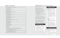
ANSI/NFPA 70-latest edition. • The installer should leave these instructions with the consumer who should retain for local inspector's use and off the electricity to the hood from the power supply before servicing or cleaning. Viking hoods are equipped with the variable speed controls for blowers. - Viking DTWS3049SS | Installation Instructions - Page 3
IMPORTANT-Please Read and Follow! WARNING TO REDUCE THE RISK OF INJURY TO PERSONS IN THE EVENT OF A RANGETOP GREASE FIRE, OBSERVE THE FOLLOWING. (Based on "Kitchen Firesafety Tips," published by NFPA.) 1. SMOTHER FLAMES with a close fitted lid, cookie sheet, or metal tray, then turn off the burner. - Viking DTWS3049SS | Installation Instructions - Page 4
Clearance Dimensions (DCH 12"H. Classic Chimney Wall Hoods w/Standard Ventilator) (913.46"cm) ((6611967675""t..mmo63 accinmmx..)) 33((783063""..t28mmoccaimmnx.)). Interior Ventilator Dimensions (DCH 12"H. Classic Chimney Wall Hoods w/Standard Ventilator) Top view A 30"W. 14-15/16" (37.9 cm) 36 - Viking DTWS3049SS | Installation Instructions - Page 5
Dimensions & Specifications (DPPV Custom Power Packs w/Standard Ventilator System) A* *For best results, center the unit over B* the burners of the cooking product (front to back; right to left). Make sure the back wall of the custom hood canopy is flush with the cutout so the ventilator - Viking DTWS3049SS | Installation Instructions - Page 6
Clearance Dimensions (DPPV Custom Power Packs w/Standard Ventilator System) (913.46"cm) ((6611967675""t..mmo63 accinmmx..)) (Custom Hood) 33((783063""..t28mmoccaimmnx.)). Interior Ventilator Dimensions (DPPV Custom Power Packs w/Standard Ventilator System) A 30"W. 14-15/16" (37.9 cm) 36"W. 17- - Viking DTWS3049SS | Installation Instructions - Page 7
-Maximum amps In-Line-Maximum amps 6.6/3.9 3.9/5.7 6.6/3.9 3.9/5.7 6.6/3.9 3.9/5.7 4.3/5.1 6.1 * A 1,200 CFM interior- or exterior-power ventilator should be used when installed over range/rangetop with gas char-grill. Max duct run is 50 ft. ** It is recommended that the 1,500 CFM ventilator be - Viking DTWS3049SS | Installation Instructions - Page 8
Interior Ventilator Dimensions (DCWH/DCWN/DCWL Classic Chimney Wall Hoods) 30"W. 33"W. 36"W. 39"W. 42"W. 45"W. 30"W. 33"W. 36"W. 39"W. 42"W. 45"W. A 10" (25.4 cm) 10" (25.4 cm) 12" (30.5 cm) 12" (30.5 cm) 12" (30.5 cm) 12" (30.5 cm) 1-1/2" (3.8 cm) B 14-15/16" (37.9 cm) 14-15/16" (37.9 cm) 17-15 - Viking DTWS3049SS | Installation Instructions - Page 9
In-Line-Maximum amps 4.7 7.4/3.9 4.7/6.6 10" (25.4 cm) 4.3 7.4/4.8/5.5 4.7/6.6 8.5 5.5/6.2 7.3 * A 1,200 CFM interior- or exterior-power ventilator should be used when installed over range/rangetop with gas char-grill. Max duct run is 50 ft. ** It is recommended that the 1,500 CFM ventilator be - Viking DTWS3049SS | Installation Instructions - Page 10
Interior Ventilator Dimensions (DCIH Classic Chimney Island Hoods) Top view 36"W. 42"W. A A 17-15/16" (45.6 cm) 20-15/16" (53.2 cm) 12" (30.5 cm) 12" (30.5 cm) 4-3/4" (12.1 cm) 4-3/4" (12.1 cm) 15" (38.1 cm) 7" (17.8 cm) dia. duct location 120 V power supply 600 CFM Interior Ventilator - Viking DTWS3049SS | Installation Instructions - Page 11
20" (50.8 cm) 3 3 VINV1200* DEV1200*/1500** DIL1200 10" (25.4 cm) 7.3 4.3/5.1 6.1 * A 1,200 CFM interior- or exterior-power ventilator should be used when installed over range/rangetop with gas char-grill. Max duct run is 50 ft. ** It is recommended that the 1,500 CFM ventilator be used with longer - Viking DTWS3049SS | Installation Instructions - Page 12
Interior Ventilator Dimensions (DTWS Slim Traditional Wall Hoods) 30"W. 36"W. 42"W. A 15-3/4" (40.0 cm) 18-3/4" (47.6 cm) 21-3/4" (55.2 cm) Top view A 1-1/8" (2.9 cm) 5-9/16" (14.3 cm) 120 V power supply 5-1/8" (13.0 cm) 7" (17.8 cm) 11" dia. duct (27.9 cm) location 300 or 600 CFM - Viking DTWS3049SS | Installation Instructions - Page 13
(121.6 cm) 3 3 VINV1200* DEV1200*/1500** DIL1200 10" (25.4 cm) 7.3 4.3/5.1 6.1 * A 1,200 CFM interior- or exterior-power ventilator should be used when installed over range/rangetop with gas char-grill. Max duct run is 50 ft. ** It is recommended that the 1,500 CFM ventilator be used with longer - Viking DTWS3049SS | Installation Instructions - Page 14
Interior Ventilator Dimensions (DTWN Tall Traditional Wall Hoods) Top view 18-3/4" (47.6 cm) A A (Duct diameter) VIV300 7" (17.8 cm)/10" (25.4 cm) VIV600 7" (17.8 cm)/10" (25.4 cm) VIV1200 10" (25.4 cm) 4-5/8" (11.7 cm) 9-1/8" (23.2 cm) 120 V 9-3/8" 9-5/8" (23.8 cm) (24.4 cm) Tall - Viking DTWS3049SS | Installation Instructions - Page 15
amps 2.8/3.8 6.6/3.9 3.9/5.7 10" (25.4 cm) 2.8/3.8 3.8 6.6/3.9 6.6/3.9 3.9/5.7 3.9/5.7 6.8 4.3/5.1 6.1 * A 1,200 CFM interior- or exterior-power ventilator should be used when installed over range/rangetop with gas char-grill. Max duct run is 50 ft. ** It is recommended that the 1,500 CFM - Viking DTWS3049SS | Installation Instructions - Page 16
Clearance Dimensions (DBCV Wall Custom Ventilator System) (913.46"cm) ((7611268672""t..mmo69 accinmmx..)) (Custom Hood) 33((796061""..t24mmoccaimmnx.)). NOTE: For best performance, it is recommended that the bottom of the hood be 30" (76.2 cm) to 36" (91.4 cm) above the countertop. These - Viking DTWS3049SS | Installation Instructions - Page 17
54" 6 3 VINV1200* DEV1200*/1500** DIL1200 10" (25.4 cm) 6.9 5.2/6.0 7.0 * A 1,200 CFM interior- or exterior-power ventilator should be used when installed over range/rangetop with gas char-grill. Max duct run is 50 ft. ** It is recommended that the 1,500 CFM ventilator be used with longer duct runs - Viking DTWS3049SS | Installation Instructions - Page 18
Installing Hood Canopy (Custom Hood Canopy Cutouts) Custom Hood Canopy A B 1) Position ventilator system inside of the custom hood canopy and center it front to back and left to right. 2) Bottom mounting holes fasten ventilator system to bottom of custom hood canopy with the screws provided. Built - Viking DTWS3049SS | Installation Instructions - Page 19
Built-In Island Custom Ventilator System Dimensions (36"W./42"W. DICV Models) 11" (27.9 cm) 8" (20.3 cm) 1" (2.5 cm) 11" (27.9 cm) 7" (17.8 cm) 1" (2.5 cm) 5" (12.7cm) 11-3/4" (29.8 cm) 900, 1200 or 1500 CFM External** or In-Line Ventilator Installation A B C 16" (40.6 cm) 6" (15.2 cm) 2" - Viking DTWS3049SS | Installation Instructions - Page 20
heights of ceilings, soffits, cabinets, or ranges/rangetops. Proper installation of ducting is extremely ventilator kit rating; all products must be hard wired direct with 2-wire with ground. Check Framing NOTE: Because Run 120 VAC electrical wiring from service panel to installation location. See - Viking DTWS3049SS | Installation Instructions - Page 21
6 5/16" nut driver CAUTION: Secure vent hood to wall using screws provided. Use additional mounting screws and wall anchors, if necessary. 7 BARE OR GREEN WHITE WHITE GREEN BLACK BLACK 5/16" nut driver CAUTION: If not using a duct cover, using screws provided make sure top mounting screws are - Viking DTWS3049SS | Installation Instructions - Page 22
. If you have any questions, contact the manufacturer. • Before servicing or cleaning unit, switch power off at service panel and lock service panel to prevent power from being switched on accidentally. When the service disconnecting means cannot be locked, securely fasten a prominent warning device - Viking DTWS3049SS | Installation Instructions - Page 23
into soffit or cabinet frame. Use additional mounting screws, if necessary. 44 To install ventillation kit refer to ventillation kit installation instructions. 5 1 4 1 2 3 Slide filter front over front lip. Push filter rear up, then slide back over rear lip. 6 1 2 3 Slide spacer front over - Viking DTWS3049SS | Installation Instructions - Page 24
Before servicing or cleaning unit, switch power off at service panel and lock service panel to prevent power from being switched on accidentally. When the service disconnecting kit refer to ventillation kit installation instructions. Replace electrical box cover. Make connection to breaker box. 47 - Viking DTWS3049SS | Installation Instructions - Page 25
6 1 7 1 3 2 Slide filter front over front lip. Push filter rear up, then slide back over rear lip. 8 1 2 3 Slide spacer front over front lip. Push spacer rear up, then slide back over rear lip. NOTE: Number of spacers and baffles may vary by model. 2 3 Slide filter front over front lip. Push - Viking DTWS3049SS | Installation Instructions - Page 26
. (Option A) Using threaded rod for additional support. (Option B) Attaching hood directly to soffit or duct cover. (Skip to step down past the cover. To install ventillation kit refer to ventillation kit installation instructions. Attach canopy to duct cover/soffit. From inside of hood, seal top - Viking DTWS3049SS | Installation Instructions - Page 27
& Parts Only authorized replacement parts may be used in performing service on the appliance. Do not repair or replace any part of the appliance unless specifically recommended in the manual. All other servicing should be referred to a qualified technician. Record the following information indicated - Viking DTWS3049SS | Installation Instructions - Page 28
54 55
-
 1
1 -
 2
2 -
 3
3 -
 4
4 -
 5
5 -
 6
6 -
 7
7 -
8
-
9
-
10
-
11
-
12
-
13
-
14
-
15
-
16
-
17
-
18
-
19
-
20
-
21
-
22
-
23
-
24
-
25
-
26
-
27
-
28
 |
 |

Viking Range Corporation
111 Front Street
Greenwood, Mississippi 38930 USA
(662) 455-1200
For product information,
call 1-888-VIKING1 (845-4641)
or visit the Viking Web site at
vikingrange.com
F20472D EN
(022410)
U
L
C
U
L
Viking Installation Guide
Designer Hoods