Viking RDMOR200SS Installation Instructions
Viking RDMOR200SS Manual
 |
View all Viking RDMOR200SS manuals
Add to My Manuals
Save this manual to your list of manuals |
Viking RDMOR200SS manual content summary:
- Viking RDMOR200SS | Installation Instructions - Page 1
Viking Installation Guide IMPORTANT-Please Read and Follow! • Please read all instructions thoroughly before installing the Built-In Microwave Hood do not operate the oven and contact your dealer or Viking AUTHORIZED SERVICER. 1 Mounting Space This Built-in Microwave Hood requires a mounting space - Viking RDMOR200SS | Installation Instructions - Page 2
directly above the Built-in Microwave Hood mounting location as shown in figure 2. NOTE: • If you have any questions about the grounding or electrical instructions, consult a qualified electrician or serviceperson. • Neither Viking nor the dealer can accept any liability for damage to the oven - Viking RDMOR200SS | Installation Instructions - Page 3
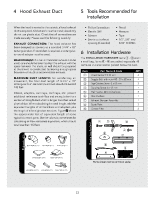
Bits When the hood is vented to the outside, a hood exhaust duct All items are in a small carton packed below the oven. Item Part Name & Code Wood Screw 5 X 35 Screw 5 x 85 mm Tapping Screw 4 x 12 mm Flat Washer 30 mm diameter Rear Cushion Exhaust Damper Assembly Scale Plate Grease Filter QTY 4 - Viking RDMOR200SS | Installation Instructions - Page 4
3. Remove Fan Cover Bracket by sliding it in the opposite direction of the arrow on the Fan Cover Bracket. Hood Fan Unit Oven for Installation) This Built-in Microwave Hood is designed for adaptation to three types of hood ventilation systems. Select the type required for your installation - Viking RDMOR200SS | Installation Instructions - Page 5
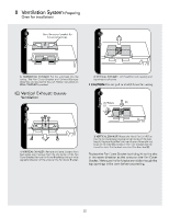
figure figure Save fan cover bracket for future instructions. ! " (A) Rotate 90˚ (B) 9 figure 3) VERTICAL EXHAUST: Rotate the Hood Fan Unit 90˚ so that the fan blade openings are facing the top of the oven. See (A). Replace Hood Fan Unit into the oven. Be careful not to pinch the lead wire - Viking RDMOR200SS | Installation Instructions - Page 6
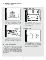
it into the slits in the same direction as the arrow. Use 1 Tapping Screw 4 x 12 mm 4 from the INSTALLATION HARDWARE and tighten into place. Mounting Plate 9 Oven Installation This oven cannot be properly installed without referring to the mounting instructions found on wall and top cabinet - Viking RDMOR200SS | Installation Instructions - Page 7
. Use Wood Screws 1 to attach the Mounting Plate to studs. 1) MOUNTING OVEN TO THE WALL: Place carton upside down. NOTE: Before insertion, be sure the correct position before insertion. + figure (A) ) figure (B) 2) MOUNTING OVEN TO THE WALL: Using cutting line around the carton, cut into two - Viking RDMOR200SS | Installation Instructions - Page 8
are recommended to attach the Built-in Microwave Hood to the Mounting Plate. . figure figure 3 5 5) MOUNTING OVEN TO THE WALL: Use the two section PREPARATION OF THE OVEN, Figure 4. Install the two Grease Filters 9. Checklist for Installation Viking Range Corporation 111 Front Street Greenwood - Viking RDMOR200SS | Installation Instructions - Page 9
Viking Instructions d'installation IMPORTANT-S'il vous plaît lisez et suivez! • Veuillez lire attentivement toutes les instructions avant d'installer le système de Micro-onde intégrée. Nous recommandons que deux personnes collaborent - Viking RDMOR200SS | Installation Instructions - Page 10
avoir des poteaux muraux de 2 x 4 po et une cloison sèche ou un plâtrage d'au moins 3/8 po (9,5 mm) d'épaisseur. Les surfaces de montage doivent pouvoir supporter un poids de 110 lb. (50 kg) - le four et son contenu - ET le poids de tous les articles qui sont normalement entreposés dans l'armoire - Viking RDMOR200SS | Installation Instructions - Page 11
4 Conduit d'évacuation - Viking RDMOR200SS | Installation Instructions - Page 12
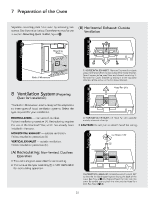
7 Préparation du four Détachez la plaque de montage du four en retirant deux vis.Voir l'illustration ci-dessous. Conservez ces vis pour les utiliser - Viking RDMOR200SS | Installation Instructions - Page 13
8 Système de Ventilation (Préparation du four pour l'installation) 8 schéma Conservez le support de fermeture de ventilateur pour des instructions ultérieures. 2) Échappement Vertical: Levez l'unité de ventilation de hotte avec précautions et glissez les fils hors de la cavité. • ATTENTION : - Viking RDMOR200SS | Installation Instructions - Page 14
8 Système de Ventilation (Préparation du four pour l'installation) 9 Installation du Four # schéma 4) Échappement Vertical: Fixez le suppor t de couverture de ventilateur - Viking RDMOR200SS | Installation Instructions - Page 15
10 Montage Mural du Four ( schéma L'utilisation du carton peut faciliter l'installation. Deje espacio superior al espesor de pared ~ schéma Côté Supérieur Pared Ligne de découpage 2) PLAQUE DE MONTAGE: Positionnez la plaque de montage avec les boulons - Viking RDMOR200SS | Installation Instructions - Page 16
10 Montage Mural du Four Il recommandé d'utiliser deux personnes pour placer le four - Viking RDMOR200SS | Installation Instructions - Page 17
Viking Superior. Lea los documentos anexos y GUARDE el Manual de Operación. Revise el horno en cuanto a su distribuidor o PROVEEDOR DE SERVICIO AUTORIZADO DE Viking. Véase las Instrucciones de Instalación para obtener . 1 12" figura 30" 15.5" 30" ó más con respecto a la superficie de cocinado Salpicadero - Viking RDMOR200SS | Installation Instructions - Page 18
la Figura 2. NOTA: • Si tiene preguntas acerca de las instrucciones eléctricas o de conexión a tierra, consulte un electricista calificado. • Ni Viking ni el distribuidor pueden aceptar ninguna responsabilidad por daño al horno o por lesiones personales resultantes de no seguir los procedimientos - Viking RDMOR200SS | Installation Instructions - Page 19
#10 - 24 x 50 mm Tornillo del Gabinete Superior, 5 x 85 mm Tornillo Auto-Perforante de 4 x 12 mm Arandela Plana con diámetro de 30 mm Cojín Trasero Regulador de Succión de Extracción Placa de Escala Filtro de Grasa Cant. 4 4 2 1 2 1 1 2 2 1 2 3 4 5 6 7 8 9 figura 90˚ Codo (10 pies.) 45˚ Codo - Viking RDMOR200SS | Installation Instructions - Page 20
7 Preparación del horno Separe la placa de montaje del horno retirando dos tornillos. Véase la Figura a continuación. Guarde estos tornillos para usarlos en la sección MONTAJE DEL HORNO EN LA PARED, paso /. (B) Escape Horizontal: Extracción hacia el exterior 5 figura 1) Escape Horizontal: - Viking RDMOR200SS | Installation Instructions - Page 21
8 Sistema de Escape (Preparación del horno para Instalación) 7 figura (A) Gire 180˚ (C) Escape Vertical: Extracciòn hacia el exterior (B) 9 figura 1) Escape Vertical: Remueva y guarde los 2 tornillos del borde trasero y los 3 tornillo de la parte central superior de la Cubierta del Ventilador - Viking RDMOR200SS | Installation Instructions - Page 22
8 Sistema de Escape (Preparación del horno para Instalación) Coloque nuevamente la Cubierta del Ventilador deslizándola dentro de las ranuras en la misma dirección de la flecha indicada sobre la Cubierta del Ventilador. Asegúrese que las aspas del ventilador son visibles a través de las aberturas - Viking RDMOR200SS | Installation Instructions - Page 23
9 Instalación del Horno 10 Montaje del Horno en la Pared Utilization of the carton may make installation easier. ( figura Pared Lado Superior Línea de Corte 2) Placa de Montaje: Coloque la Placa de Montaje con los Pernos de Anclaje sujetados, en el sitio de pared e inserte los Pernos y Tuercas - Viking RDMOR200SS | Installation Instructions - Page 24
placa inferior que guardo previamente de acuerdo a las indicaciones de la sección Preparación del horno. Instale los dos Filtros de Grasa 9. Viking Range Corporation 111 Front Street Greenwood, Mississippi 38930 USA (662) 455-1200 Para mayor información sobre productos, llame al 1-888-VIKING1 (845
-
 1
1 -
 2
2 -
 3
3 -
 4
4 -
 5
5 -
 6
6 -
 7
7 -
8
-
9
-
10
-
11
-
12
-
13
-
14
-
15
-
16
-
17
-
18
-
19
-
20
-
21
-
22
-
23
-
24
 |
 |

Viking Installation Guide
D3 Built-In Microwave Hood
111 Front Street
Greenwood, Mississippi 38930 USA
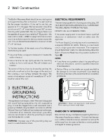
IMPORTANT–Please Read and Follow!
•
Please read all instructions thoroughly before installing the Built-In Microwave Hood. Two people are
recommended to install this product.
•
If a new electrical outlet is required, its installation should be completed by a qualified electrician before the
Built-In Microwave Hood is installed. See
ELECTRICAL GROUNDING INSTRUCTIONS
on page 2.
Open the bottom of the carton, bend the carton flaps
back and tilt the oven over to rest on plastic foam pad.
Lift carton off oven and remove all packing materials,
Wall and Top Cabinet Template, Turntable, and Turntable
Support. SAVE THE CARTON AS IT MAY MAKE
INSTALLATION EASIER.
•
Remove the feature sticker from the outside of the
door, if there is one.
•
DO NOT REMOVE THE WAVEGUIDE COVER, which
is located on the right side wall of the oven cavity.
Check to see that there is a Wall TEMPLATE and Top
CABINET Template. Read enclosures and SAVE the
Use and Care manual.
Check the oven for any damage, such as misaligned or
bent door, damaged door seals and sealing surfaces,
broken or loose door hinges and latches and dents inside
the cavity or on the door. If there is any damage, do
not operate the oven and contact your dealer or Viking
AUTHORIZED SERVICER.
Unpacking and Examining
Your Oven
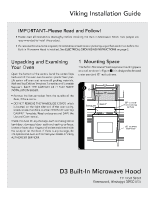
1 Mounting Space
This Built-in Microwave Hood requires a mounting space
on a wall as shown in Figure
1
. It is designed to be used
under standard 12" wall cabinets.
Backguard
At least 2"
15.5"
30"
12"
30" or more
from cooking
surface
66" or more
from floor
1