Viking RDMOS201SS 30 inch W. Built-In Trim Kit - Installation Instructions
Viking RDMOS201SS Manual
 |
View all Viking RDMOS201SS manuals
Add to My Manuals
Save this manual to your list of manuals |
Viking RDMOS201SS manual content summary:
- Viking RDMOS201SS | 30 inch W. Built-In Trim Kit - Installation Instructions - Page 1
Viking Installation Guide D3 Microwave Built-In Trim Kit - Viking RDMOS201SS | 30 inch W. Built-In Trim Kit - Installation Instructions - Page 2
and ordinances. • The installer should leave these instructions with the consumer who should retain for local inspector's use and for future reference. WARNING This built-in trim kit is designed for use only with Viking microwave ovens specifying builtin trim kit RDMTK302 on the rating label on the - Viking RDMOS201SS | 30 inch W. Built-In Trim Kit - Installation Instructions - Page 3
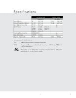
Amp Usage Approx. Shipping Wt. Microwave Oven RDMOS201 24" (60.9 cm) 13-3/8" (33.9 cm) 19-1/8" (48.7 cm) Width Height Depth Overall 17-3/8" 10-1/2" 18-5/8" 2.0 cu. ft. (44.1 cm) (26.6 cm) (47.3 cm) 120VAC/60 Hz 1.5 KW 13 amps 46 lbs. (20.9 kg) Built-In Trim Kit RDMTK302 29-1/2" (74.9 cm - Viking RDMOS201SS | 30 inch W. Built-In Trim Kit - Installation Instructions - Page 4
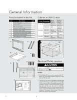
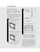
FLOOR LINE OF CUTOUT OPENING CENTER LINE BUILT-IN TRIM KIT FLUSH MOUNTING TEMPLATE FOR DESIGNER SERIES MICROWAVE OVEN 1. Align the Flush Mounting Template center line of the opening should be constructed of plywood strong enough to support the weight of the oven and floor load (approximately 100 - Viking RDMOS201SS | 30 inch W. Built-In Trim Kit - Installation Instructions - Page 5
Flush Mount Configuration Microwave Oven and Frame Assembly A glaFsslaure sfluhsh wmithothue cnabtinect onfiguration- Microwave Oven and Frame and one (1) bottom spacer are required. Spacers are not included in the kit and must be fabricated by installer. See figures 3A and B for spacer - Viking RDMOS201SS | 30 inch W. Built-In Trim Kit - Installation Instructions - Page 6
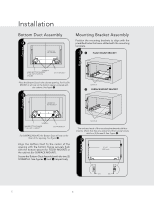
Installation Illustration 6 - for Flush Mount Bottom Duct Assembly 4 CENTER THE BOTTOM DUCT Mounting Bracket Assembly Position the mounting brackets to align with the predrilled holes that were drilled with the mounting template. 6A Flush mount BRACKET figure figure SCREW A make bottom flange - Viking RDMOS201SS | 30 inch W. Built-In Trim Kit - Installation Instructions - Page 7
to locate the 4 ball studs. ! 4 BALL STUDS On BACK OF FRAME ASSEMBLY SMALL STAINLESS DECORATIONS ON TOP figure figure CABINET INSTALL Carefully guide the assembled oven into the prepared opening. Slide the oven onto the Bottom Duct Assembly. See figure 8. 9 FOOT BOTTOM DUCT ASSEMBLY DUCT RECESS - Viking RDMOS201SS | 30 inch W. Built-In Trim Kit - Installation Instructions - Page 8
Make sure the unit has been installed according to all of the Installation Instructions and the required Mounting Template. 2. Plug in the power cord. 3. Keep the Use & Care Manual and Installation Manual. Viking Range Corporation 111 Front Street Greenwood, Mississippi 38930 USA (662) 455-1200 For - Viking RDMOS201SS | 30 inch W. Built-In Trim Kit - Installation Instructions - Page 9
Guide d'installation Viking Kit de garniture à encastrer pour four à micro-ondes D3 - Viking RDMOS201SS | 30 inch W. Built-In Trim Kit - Installation Instructions - Page 10
devra les conserver pour l'usage d'un inspecteur local et pour référence ultérieure. AVERTISSEMENT Ce kit à encastrer est conçu pour être utilisé uniquement avec les fours à micro-ondes viking spécifiant kit à encastrer RDMTK302 sur l'étiquette des spécifications nominales sur la paroi gauche de la - Viking RDMOS201SS | 30 inch W. Built-In Trim Kit - Installation Instructions - Page 11
èrage max. 1,5 KW 13 amps Poids approx. à l'expédition. 46 lb. (20,9 kg) Kit de garniture à encastrer RDMTK302 29-1/2 po (749 mm) 17-1/4 po (437 mm) S/O S/O 15 . DHHS - Conforme au règlement du Department of Health and Human Services (DHHS), CFR, Titre 21, Chapitre I, Souschapitre J. - Ce - Viking RDMOS201SS | 30 inch W. Built-In Trim Kit - Installation Instructions - Page 12
LINE OF CUTOUT OPENING CENTER LINE BUILT-IN TRIM KIT FLUSH MOUNTING TEMPLATE FOR DESIGNER SERIES MICROWAVE OVEN 1. Align the Flush Mounting Template center Le plancher de l'ouverture doit être en contreplaqué assez fort pour supporter le poids du four et sa propre charge (environ 45,5 kg [100 - Viking RDMOS201SS | 30 inch W. Built-In Trim Kit - Installation Instructions - Page 13
Illustration 2 2 Aa. FluCshoMonunftiCgonufigruraattioino- n pour fixation Microwave Oven and Frame Assembly glaessnarecflaussh twitrh éthee c-abLineetfour (1) entretoise inférieure. Les entretoises ne sont pas fournies dans le kit et doivent être fabriquées par l'installateur. Voir figures 3A et - Viking RDMOS201SS | 30 inch W. Built-In Trim Kit - Installation Instructions - Page 14
Installation Illustration 6 - for Flush Mount Conduit inférieur 4 CCENETNETRRTEHRE LE BOCTTOONMDDUUICTT INFÉRIEUR Brides de fixation Placer les brides de fixation pour les aligner avec les trous percés à l'aide du gabarit. 6A Bride fixée encastrée figure figure VIS A FAIRE AFFLEURER LA BRIDE - Viking RDMOS201SS | 30 inch W. Built-In Trim Kit - Installation Instructions - Page 15
STALL Installation Aligner les brides de fixation horizontalement en les faisant glisser vers l'avant et l'arrière le long des fentes de vis jusqu'à ce que les brides soient exactement séparées de 27-1/2 po (698,5 mm) et à égale distance des côtés de l'armoire. Voir figure 7. Une fois les brides - Viking RDMOS201SS | 30 inch W. Built-In Trim Kit - Installation Instructions - Page 16
contrôle 1. Veiller à ce que l'appareil soit installé selon les instructions et avec le bon gabarit de fixation. 2. Brancher le cordon d'alimentation. 3. le mode d'emploi et d'entretien et le manuel d'installation Viking Range Corporation 111 Front Street Greenwood, Mississippi 38930 USA - Viking RDMOS201SS | 30 inch W. Built-In Trim Kit - Installation Instructions - Page 17
Guía de instalación Viking Juego de molduras para empotrado del Microondas D3 - Viking RDMOS201SS | 30 inch W. Built-In Trim Kit - Installation Instructions - Page 18
Tabla de Contenido Advertencias e información importante 18 Especificaciones 19 Información general 20 Partes incluidas en el juego 20 Abertura del gabinete o pared 20 Ubicación del tomacorriente eléctrico 20 Instalación 21 Plantilla de montaje 21 Conjunto de ducto inferior 21 Ensamblaje - Viking RDMOS201SS | 30 inch W. Built-In Trim Kit - Installation Instructions - Page 19
Especificaciones Ancho total Altura total desde la parte inferior Profundidad total desde la parte posterior Parte interna del horno Requisitos eléctricos Cap. máx. en amperios Peso de despacho aprox. Horno microondas 24" 13-3/8" RDMOS201 (60.9 cm) (33.9 cm) Juego de molduras para empotrado - Viking RDMOS201SS | 30 inch W. Built-In Trim Kit - Installation Instructions - Page 20
Offset 1/4" (6.35 mm) 14" (355.9 mm) 14-13/16" (376.2 mm) FLOOR LINE OF CUTOUT OPENING CENTER LINE BUILT-IN TRIM KIT FLUSH MOUNTING TEMPLATE FOR DESIGNER SERIES MICROWAVE OVEN 1. Align the Flush Mounting Template center line with the center of the cabinet. Align the Floor Line with the bottom of - Viking RDMOS201SS | 30 inch W. Built-In Trim Kit - Installation Instructions - Page 21
figura figura 13-1/2" min. Instalación Plantilla de montaje Determine el método de montaje a usar en base a la configuración requerida. Vea la figura 2A para MONTAJE AL RAS y 2B para MONTAJE EN SUPERFICIE. Alinee la plantilla correspondiente al método de montaje necesario en el centro del - Viking RDMOS201SS | 30 inch W. Built-In Trim Kit - Installation Instructions - Page 22
figura Instalación Illustration 6 - for Flush Mount Conjunto del Ducto Inferior 4 CENTCEERNTHTERE EL BDOUTTCOTMODINUCFTERIOR Ensamblaje del soporte de montaje Coloque los soportes de montaje para que se alineen con los agujeros taladrados preparados con la plantilla de montaje. 6 A SOPORTE PARA - Viking RDMOS201SS | 30 inch W. Built-In Trim Kit - Installation Instructions - Page 23
STALL Instalación Alinee los soportes de montaje horizontalmente deslizándolos hacia atrás y hacia adelante a través de las ranuras de los tornillos hasta que los soportes tengan una distancia exacta de 27-1/2" entre sí y una distancia igual desde los lados del gabinete. Vea la Figura 7. Una vez - Viking RDMOS201SS | 30 inch W. Built-In Trim Kit - Installation Instructions - Page 24
las instrucciones de instalación y la plantilla de montaje necesaria. 2. Enchufe el cable de alimentación. 3. Conserve el Manual de uso y cuidado y el Manual de instalación Viking Range Corporation 111 Front Street Greenwood, Mississippi 38930 EE.UU. (662) 455-1200 Para mayor información sobre
-
 1
1 -
 2
2 -
 3
3 -
 4
4 -
 5
5 -
 6
6 -
 7
7 -
8
-
9
-
10
-
11
-
12
-
13
-
14
-
15
-
16
-
17
-
18
-
19
-
20
-
21
-
22
-
23
-
24
 |
 |

Viking Installation Guide
D3 Microwave Built-In Trim Kit