Viking VMOC206SS Installation Instructions
Viking VMOC206SS Manual
 |
View all Viking VMOC206SS manuals
Add to My Manuals
Save this manual to your list of manuals |
Viking VMOC206SS manual content summary:
- Viking VMOC206SS | Installation Instructions - Page 1
instructions with the consumer who should retain for local inspector's use and for future reference. • This built-in trim kit is designed for use only with Viking convection and Conventional microwave ovens specifying built-in trim kit BUILT-IN TRIM KIT TEMPLATE FOR CUSTOM SERIES MICROWAVE OVEN - Viking VMOC206SS | Installation Instructions - Page 2
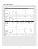
Basic Specifications Microwave Oven Built-In Custom Trim Kits Description CONVECTION VMOC206 VMTK277 VMTK307 VMTK367 Overall Width 24-5/8" (62.5 cm) 26-1/2" (67.3 cm) 29-1/2" (74.9 cm) 35-1/4" (89.5 cm) Overall Height from Bottom 14-7/8" (37.7 cm) - Viking VMOC206SS | Installation Instructions - Page 3
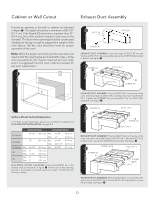
be constructed of plywood strong enough to support the weight of the oven (about 100 Secure together by using a SCREW (A) provided in the kit. See figure 2. 3 SCREW (A) DUCT (A)-1 DUCT ( template and flush mount installation on page 5-6. CONVECTION CONVENTIONAL (A) Height 18-1/2" (46.9 cm) Min - Viking VMOC206SS | Installation Instructions - Page 4
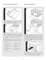
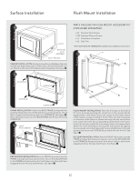
with the two (¾") screws (C). 7 CABINET INSTALLATION: Place the oven adjacent to the wall or cabinet opening. Plug the power cord into the electrical outlet. Carefully guide the assembled oven into the prepared opening. Slide the oven on the Bottom Duct Assembly. See figure 7. E4 - Viking VMOC206SS | Installation Instructions - Page 5
Assembly. See figure 8. 9 Parts included in flush mount accessory kit (PURCHASED SEPARATELY): • (2) Stainless Steel Scoops • (10) Stainless Machine Screws • (1) Flush Mount Template • (2) Side Trim * See FLUSH MOUNT Template for additional installation instructions. " SCREW (B) SCREW (B) SCREW - Viking VMOC206SS | Installation Instructions - Page 6
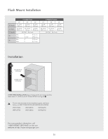
Flush Mount Installation CONVECTION 27" 30" 36" (A) Height 21-5/16" (542 cm) 21-5/16" Microwave opening Lower Oven Opening OVER OVEN INSTALLATION: Space between the microwave and the lower oven: 2" (5.08 cm) for 27"W and 30"W. See Figure #. The trim kits described in this installation guide, - Viking VMOC206SS | Installation Instructions - Page 7
Ce kit à encastrer est destiné à être utilisé UNIQUEMENT AVEC LES FOURS À MICRO-ONDES TRADITIONNELS ET À CONVECTION VIKING SPÉCIFIANT KIT À Maximum Cutout Opening Height 17" (431.8 mm) BUILT-IN TRIM KIT TEMPLATE FOR CUSTOM SERIES MICROWAVE OVEN Center Line USE THIS SIDE OF TEMPLATE FOR MODELS - Viking VMOC206SS | Installation Instructions - Page 8
Spécifications de Base Four à micro-ondes Kits de garniture à encastrer Descriptión CONVECTION VMOC206 VMTK277 VMTK307 VMTK367 Largeur hors tout 24-5/8 po (62,5 cm) 26-1/2 po (67,3 cm) 29-1/2 po (74,9 cm) 35-1/4 po (89,5 cm) Hauteur hors - Viking VMOC206SS | Installation Instructions - Page 9
l'ouverture doit être en contreplaqué assez fort pour supporter le poids du four et sa propre charge (environ ensemble à l'aide d'une VIS (A) fournis dans le kit. Voir schéma 2. 3 CONDUIT (A)-1 VIS (A) sch POUR MONTAGE ENCASTRÉ à la page 12. CONVECTION TRADITIONNEL (A) Hauteur 18-1/2 po (46,9 cm - Viking VMOC206SS | Installation Instructions - Page 10
d'évacuation 5A Installation en surface 6 schéma schéma VIS C ENSEMBLE DU CONDUIT D'ÉVACUATION ASSEMBLAGE DU CONDUIT D'ÉVACUATION : Retirer les coussins du support adhésif. Appliquer les coussins aux brides de l'ensemble conduit comme indiqué par les flèches. Voir schéma 5A. 5B écart "A" sch - Viking VMOC206SS | Installation Instructions - Page 11
Installation en surface 7 9 VIS (B) VIS (B) schéma schéma POSE DANS L'ARMOIRE : Placer le four près de l'ouverture du mur ou de l'armoire. Brancher le cordon d'alimentation dans la prise électrique. Guider avec précaution le four assemblé dans l'ouverture préparée. Faire glisser le four sur l' - Viking VMOC206SS | Installation Instructions - Page 12
cm (30 po) de large. Voir schéma ". Les kits à encastrer décrits dans ce guide d'installation, et indiqués ci-dessous, NE DOIVENT PAS ÊTRE et serrer avec la VIS (B) incluse dans le kit. Voir figure ". (A) Hauteur (B) Largeur (C) Profondeur (D) (E) CONVECTION 27 po 30 po 36 po 21-5/16 po - Viking VMOC206SS | Installation Instructions - Page 13
SÓLO CON HORNOS MICROONDAS DE CONVECCIÓN VIKING Y CONVENCIONALES QUE ESPECIFIQUEN EL JUEGO DE en la etiqueta de potencia en la placa de la parte inferior de la cavidad del horno. • El horno puede 17" (431.8 mm) BUILT-IN TRIM KIT TEMPLATE FOR CUSTOM SERIES MICROWAVE OVEN Center Line USE THIS SIDE - Viking VMOC206SS | Installation Instructions - Page 14
ón CONVECCIÓN VMOC206 VMTK277 VMTK307 VMTK367 Ancho total 24-5/8" (62,5 cm) 26-1/2" (67,3 cm) 29-1/2" (74,9 cm) 35-1/4" (89,5 cm) Altura total desde la parte inferior 14-7/8" (37,7 cm) 19-13/16" (50,1 cm) 19-13/16" (50,1 cm) 19-13/16" (50,1 cm) Profundidad total desde la - Viking VMOC206SS | Installation Instructions - Page 15
) (12,7 cm) UBICACIÓN DEL TOMACORRIENTE ELÉCTRICO: El tomacorriente NO debe estar en el área sombreada como se indica en la figura 1. En la parte posterior de la abertura, debe haber un tomacorriente eléctrico de tres clavijas polarizado de 115-120 volt CA, 15 amperios o mayor. TORNILLO (A) DUCTO - Viking VMOC206SS | Installation Instructions - Page 16
ducto inferior de VMTK277SS, 307SS o 376SS esté colocado correctamente en la abertura, el borde frontal del conjunto del ducto estará al ras con la parte frontal del gabinete. 2 El VMTK272SS, 302SS o 372SS del DUCTO DE ESCAPE será coloca correctamente cuando el borde de la ducto está empotrado 5mm - Viking VMOC206SS | Installation Instructions - Page 17
marco. Asegure las paletas al marco con 6 tornillos de máquina proporcionados en el juego de accesorios. Coloque las molduras laterales en la parte posterior del marco como se muestra en la imagen y alinee los agujeros de los tornillos del lado superior e inferior con los correspondientes agujeros - Viking VMOC206SS | Installation Instructions - Page 18
Instalación del montaje al ras (A) Altura (B) Peso (C) Profundidad (D) (E) CONVECCIÓN 27" 30" 36" 21-5/16" (542 cm) 21-5/16" (542 cm) 21-5/16" (542 cm) 26-15/16" (68,3 cm) 29-15/16" (76 cm) 35-5/8" (90,4 cm) 22-1/16" (56,1 cm) mín, 6" (15,2 cm) máx, 11-1/2" (29,2 cm) mín, 4" (10 - Viking VMOC206SS | Installation Instructions - Page 19
- Viking VMOC206SS | Installation Instructions - Page 20
Viking Range Corporation 111 Front Street Greenwood, Mississippi 38930 USA (662) 455-1200 TINSLB016MRR0
-
 1
1 -
 2
2 -
 3
3 -
 4
4 -
 5
5 -
 6
6 -
 7
7 -
8
-
9
-
10
-
11
-
12
-
13
-
14
-
15
-
16
-
17
-
18
-
19
-
20
 |
 |

BUILT-IN TRIM KIT TEMPLATE
FOR CUSTOM SERIES MICROWAVE OVEN
USE THIS SIDE OF TEMPLATE FOR MODELS
VMTK272 and VMTK302 ONLY.
Viking Installation Guide
Custom Series Convection /
Conventional Microwave Built-In Trim Kit
111 Front Street
Greenwood, Mississippi 38930 USA
IMPORTANT–Please Read and Follow!
•
Before beginning, please read these instructions completely and carefully.
•
Be sure to DISCONNECT THE PLUG of the microwave oven from the electrical outlet before installing the built-in trim kit.
Remove the turntable from the oven cavity.
•
Because the kit includes metal parts, caution should be used in handling and installation to avoid the possibility of injury.
•
Do not remove permanently affixed labels, warnings, or plates from the product. This may void the warranty.
•
Please observe all local and national codes and ordinances.
• The installer should leave these instructions with the consumer who should retain for local inspector’s use and for
future reference.
•
This built-in trim kit is designed for use ONLY WITH VIKING CONVECTION AND CONVENTIONAL MICROWAVE OVENS
SPECIFYING BUILT-IN TRIM KIT VMTK272, VMTK302, VMTK362, VMTK277, VMTK307 or VMTK367 on the rating label on
the bottom face plate of the oven cavity.
•
YOUR OVEN CAN BE BUILT INTO A CABINET OR WALL BY ITSELF OR ABOVE ANY ELECTRIC WALL OVEN OR WARMING
DRAWER.
Parts Included in VMTK kits
Front Frame
QTY 1
Back Frame
QTY 1
Front Frame Assembly
QTY 1
Bottom Duct Assembly
QTY 1
Screw A (1/2" length)
QTY 10 *
Screw B (1-3/4" length)
QTY 4
27" & 30"Surface Mount
Template 2-sided
or 36"Surface Mount
Template single-sided
QTY 1
Cushion QTY 3
Duct (A)-1
QTY 1 *
Duct (A)-3
QTY 1 *
Duct (B)
QTY 1 *
*
Duct (C)
QTY 1 *
Duct (A)-2
QTY 1 *
Screw C (3/4" length)
QTY 2
*
VMTK277, VMTK307 and VMTK367
ONLY
.