Weber Summit Gold A Owner Manual - Page 8
Summit, Silver A Exploded View List - igniter button
 |
View all Weber Summit Gold A manuals
Add to My Manuals
Save this manual to your list of manuals |
Page 8 highlights
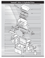
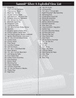
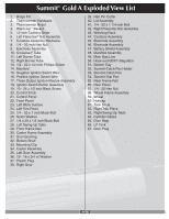
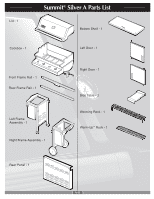
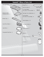
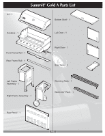
Summit® Silver A Exploded View List 1. Hinge Pin 2. Thermometer Hardware 3. Thermometer Bezel 4. Warm-Up™ Basket 5. 12 inch Cooking Grate 6. Left Flavorizer® Bar Assembly 7. Cookbox Assembly Hardware 8. 1/4 - 20 inch Hex Nut 9. Electrode Assembly 10. Crossover® Tube 11. Left Burner Tube 12. 1/4 - 20 x 1/2 inch Phillips Screw 13. Manifold 14. Negative Ignition Switch Wire 15. Positive Ignition Switch Wire 16. Two Output Ignition Module Assembly 17. Ignition Switch Button Assembly 18. 10 - 24 x 1/2 inch Black Screw 19. Control Knob 20. Control Panel 21. Front Panel 22. Left Work Surface 23. Left Trim Piece 24. 1/4 - 20 x 1 inch Black Bolt 25. Nylon Washer 26. 1/4 - 20 x 1/2 inch Black Bolt 27. Left Swing-Up Table 28. Front Frame Rail 29. Caster Frame Assembly 30. Door Bushing 31. Bottom Shelf 32. Mounting Clip 33. Caster Assembly 34. Left Door Assembly 35. 10 -16 x 3/4 Screw w/ Washer 36. Plastic Plug 37. Right Door 38. Hair Pin Cotter 39. Lid Assembly 40. 1/4 - 20 x 1 1/4 inch Bolt 41. Right Flavorizer® Bar Assembly 42. Warming Rack 43. Cooking Box Assembly 44. Electrode Assembly 45. Right Burner Tube 46. Battery Shield Assembly 47. Manifold Assembly 48. Main Gas Line 49. Hose and QCC1 Regulator 50. Bottom Tray 51. Summit Catch Pan Holder 52. Summit Catch Pan 53. Summit Drip Pan 54. Rear Frame Rail 55. Rear Panel 56. Wheel Frame Assembly 57. 1/4 - 20 Hex Nut 58. Hubcap 59. Wheel 60. Tank Scale 61. Right Trim Piece 62. Cylinder Glides 63. Right Swing-Up Table 64. Door Stop 65. LP Tank 66. Door Plug A-8
-
 1
1 -
2
-
 3
3 -
 4
4 -
 5
5 -
 6
6 -
 7
7 -
 8
8 -
 9
9 -
 10
10 -
 11
11 -
 12
12 -
 13
13 -
14
-
15
-
16
-
17
-
18
-
19
-
20
-
21
-
22
-
23
-
24
-
25
-
26
-
27
-
28
-
29
-
30
-
31
-
32
-
33
-
34
-
35
-
36
-
37
-
38
-
39
-
40
-
41
-
42
-
43
-
44
-
45
-
46
-
47
 |
 |