Weider 9900i Uk Manual
Weider 9900i Manual
 |
View all Weider 9900i manuals
Add to My Manuals
Save this manual to your list of manuals |
Weider 9900i manual content summary:
- Weider 9900i | Uk Manual - Page 1
Serial Number Decal QUESTIONS? If you have questions, or if there are missing parts, please contact us: UK Call: 08457 089 009 From Ireland: 053 92 all precautions and instructions in this manual before using this equipment. Keep this manual for future reference. USERʼS MANUAL www.iconeurope.com - Weider 9900i | Uk Manual - Page 2
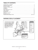
CHART 37 CABLE DIAGRAM 38 MAINTENANCE 39 EXERCISE GUIDELINES 40 PART LIST 43 EXPLODED DRAWING 45 ORDERING REPLACEMENT PARTS Back Cover WARNING DECAL PLACEMENT This drawing shows the location(s) of the warning decal(s). If a decal is missing or illegible, see the front cover of this manual - Weider 9900i | Uk Manual - Page 3
instructions in this manual exercise program, consult your physician. This is especially important for persons over age 35 or persons with pre-existing health problems. 2. Use the weight system only as described in this manual tighten all parts regularly. Replace any worn parts immediately. 8. - Weider 9900i | Uk Manual - Page 4
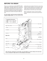
BEGIN Thank you for selecting the versatile WEIDER® 9900 I weight system. The weight system number decal are shown on the front cover of this manual. Before reading further, please review the drawing below and familiarize yourself with the parts that are labeled. Assembled Dimensions: Height: 6 ft. - Weider 9900i | Uk Manual - Page 5
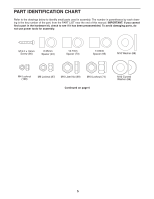
PART IDENTIFICATION CHART Refer to the drawings below to identify small parts used in assembly. The number in parentheses by each drawing is the key number of the part, from the PART LIST near the end of this manual. IMPORTANT: If you cannot find a part in the hardware kit, check to see if it has - Weider 9900i | Uk Manual - Page 6
M10 x 57mm Bolt (93) M10 x 55mm Bolt (79) M10 x 50mm Button Bolt (76) M10 x 47mm Bolt (91) M6 x 45mm Bolt (85) M10 x 45mm Bolt (98) M10 x 43mm Bolt (65) M10 x 40mm Bolt (97) M10 x 20mm Screw (84) M6 x 16mm Screw (62) M4 x 12mm Bolt (107) M10 x 57mm Bolt Set (80) M10 x 63mm Bolt (89) M8 x 65mm - Weider 9900i | Uk Manual - Page 7
instructions: • Assembly requires two persons. • Because of its weight and size, assemble the weight system in the location where it will be used. Make sure that there is enough clearance to walk around the weight system. • Place all parts small parts, use the PART IDENTIFICATION CHART on - Weider 9900i | Uk Manual - Page 8
3. Attach the U-stabilizer (3) to the Base (1) with two M10 x 68mm Bolts (66), two M10 Washers 3 (88), and two M10 Locknuts (74). 3 88 66 74 1 74 88 4. Orient the Upright (5) as shown. 4 Attach the Upright (5) to the Base (1) and the Side Stabilizers (2) with four M10 x 55mm Bolts (79), four - Weider 9900i | Uk Manual - Page 9
5. Orient the Leg (10) as shown. 5 Attach the Leg (10) to the Base (1) with two M10 x 55mm Bolts (79), two M10 Washers (88), and two M10 Locknuts (74). Do not fully tighten the Locknuts yet. 10 74 74 6. Orient the Seat Tube (8) as shown. Attach the Leg (10) to the Seat Tube (8) with two M10 - Weider 9900i | Uk Manual - Page 10
7. Apply some of the included grease to an M10 x 57mm Bolt Set (80). 7 Orient the Leg Lever (13) so that the high end of the bracket is in the location shown. Attach the Leg Lever (13) to the Leg (10) with the M10 x 57mm Bolt Set (80). Make sure that the barrel of the Bolt Set is inserted through - Weider 9900i | Uk Manual - Page 11
10. Orient the Weight Guides (31) so that the indicated holes are closer to the floor. 10 Insert the Weight Guides (31) into the holes in the Base (1). Attach each Weight Guide with an M10 x 63mm Bolt (89) and an M10 Locknut (74). Holes 31 74 74 1 89 11 - Weider 9900i | Uk Manual - Page 12
11. Orient the Bottom Cover (28) so that the notch is in the indicated location. 11 Slide the Bottom Cover (28) downward over the Weight Guides (31) and the Burn Cable (45). Make sure that the Burn Cable is routed as shown and is inserted into the notch in the Bottom - Weider 9900i | Uk Manual - Page 13
13. Slide a Bumper (40) onto each Weight Guide (31). 13 Orient a Weight (30) so that the pin hole is in the indicated location. Then, slide the Weight (30) onto the Weight Guides (31). Route the end of the Burn Cable (45) upward through the center of the Weight. Repeat these actions with the - Weider 9900i | Uk Manual - Page 14
16. Attach the Top Frame (6) to the Weight Guides 16 (31) with two M10 x 43mm Bolts (65), two M10 Curved Washers (86), and two M10 Locknuts (74). See step 15. Tighten the M10 Locknuts ( - Weider 9900i | Uk Manual - Page 15
18. Apply grease to an M10 x 130mm Bolt (11). Identify the Left and Right Press Arms (17, 18) and orient them as shown. Insert the Press Arm Spacer (42) between the Left and Right Press Arms (17, 18) as shown. Attach the Left and Right Press Arms (17, 18) to the Base (1) with the M10 x 130mm Bolt ( - Weider 9900i | Uk Manual - Page 16
20. Attach the Butterfly Frame (7) to the Top Frame (6) with two M10 x 93mm Bolts (63), two M10 20 Washers (88), and two M10 Locknuts (74). Do not fully tighten the Locknuts yet. Insert a Ball Detention Assembly (96) into the Left and Right Butterfly Arms (15, 16). 63 6 88 16 96 96 15 7 74 21 - Weider 9900i | Uk Manual - Page 17
22. Identify the Low Cable (43). Route the Low Cable through the bracket on the Leg Lever 22 (13). Attach a Pulley (69) inside the Leg Lever (13) over the Low Cable (43) with an M10 x 63mm Bolt (89), two 12.7mm Spacers (73), and an M10 Locknut (74). 13 74 73 69 43 73 89 23. Route the Low Cable - Weider 9900i | Uk Manual - Page 18
25. Route the Low Cable (43) over a Pulley (69). 25 Attach the Pulley (69) and a Cable Trap (71) inside the Left and Right Press Arms (17, 18) with an M10 x 125mm Bolt (83) and an M10 Washer (88). Make sure that the Cable Trap is oriented to hold the Low Cable in the groove of the Pulley. 69 83 - Weider 9900i | Uk Manual - Page 19
28. Identify the High Cable (44). Route the High Cable through the bracket on the Top Frame (6) 28 and over a Pulley (69). Attach the Pulley (69) inside the Top Frame (6) with an M10 x 68mm Bolt (66), two 14.8mm Spacers (95), and an M10 Locknut (74). 69 74 95 44 6 95 66 29. Route the High - Weider 9900i | Uk Manual - Page 20
31. Route the High Cable (44) around a Pulley (69). 31 Attach the Pulley (69) and a Cable Trap (71) to the Right Butterfly Pulley Bracket (21) with an M10 x 47mm Bolt (91) and an M10 Locknut (74). Make sure that the Cable Trap is oriented to hold the High Cable in the groove of the Pulley. 32. - Weider 9900i | Uk Manual - Page 21
34. Route the High Cable (44) under a V-pulley (67). 34 Attach the V-pulley (67) and a Cable Trap (71) to the Upright (5) with an M10 x 57mm Bolt (93) and an M10 Locknut (74). Make sure that the Cable Trap is oriented to hold the High Cable in the groove of the V-pulley. Route the High Cable (44) - Weider 9900i | Uk Manual - Page 22
36. Insert a Pulley (69) under the High Cable (44) in the location shown. 36 Attach the Pulley (69) and a Cable Trap (71) to the left side of the Top Frame (6) with an M10 x 93mm Bolt (63), an M10 Washer (88), and an M10 Locknut (74). Make sure that the Cable Trap is oriented to hold the High - Weider 9900i | Uk Manual - Page 23
39. Route the Low Cable (43) under a Pulley (69). 39 Attach the Pulley (69) and a Cable Trap (71) to the center bracket on the Base (1) with an M10 x 50mm Button Bolt (76), two Half Guards (72), and an M10 Locknut (74). Make sure that the Cable Trap (71) is oriented to hold the Low Cable (43) in - Weider 9900i | Uk Manual - Page 24
42. Route the Low Cable (43) under a Pulley (69). 42 Attach the Pulley (69) and a Cable Trap (71) to the front bracket on the Base (1) with an M10 x 50mm Button Bolt (76), two Half Guards (72), and an M10 Locknut (74). Make sure that the Cable Trap (71) is oriented to hold the Low Cable (43) in - Weider 9900i | Uk Manual - Page 25
44. Orient the Weight Selector (32) as shown. 44 Tighten the lower end of the Burn Cable (45) completely into the Weight Selector (32). Insert the threaded end of the High Cable (44) through the upper end of the Burn Cable (45). Tighten the High Cable (44) at least five complete turns into the - Weider 9900i | Uk Manual - Page 26
46. Insert the Weight Pin (41) under a Weight (30). 46 30 41 47. Insert the Lock Pin (39) through a Weight Guide (31) and secure the Lock (38) into the Lock Pin. 47 31 38 39 48. Orient the Seat (24) and a Cushion Frame (9) as shown. 48 - Weider 9900i | Uk Manual - Page 27
49. Insert the Cushion Frame (9) into the Seat Tube (8). 49 Tighten an Adjustment Knob (29) into the Seat Tube (8) and one of the holes in the Cushion Frame (9). Make sure that the Adjustment Knob is engaged in a hole. 9 8 29 50. Orient the Leg Lock Frame (12) as shown. Slide a Foam Pad (35) - Weider 9900i | Uk Manual - Page 28
52. Orient the Backrest (25) and a Cushion Frame (9) as shown. Attach the Backrest (25) to the Cushion Frame (9) with four M6 x 16mm Screws (62). 52 25 9 62 62 53. Insert the Cushion Frame (9) into the Upright (5). 53 Tighten an Adjustment Knob (29) into the Upright (5) and one of the holes - Weider 9900i | Uk Manual - Page 29
54. Identify the Left and Right and Butterfly Pads (22, 23). 54 Attach the Right Butterfly Pad (23) to the Right Butterfly Arm (16) with two M6 x 16mm Screws (62). 23 Attach the Left Butterfly Pad (22) to the Left 16 Butterfly Arm (15) in the same way. 62 15 22 55. Slide a Foam Pad (35) - Weider 9900i | Uk Manual - Page 30
56. Note: For clarity, the Top Cover (27) is not shown in steps 56 to 58. 56 Identify the Center Shroud (33) and the Right and Left Side Shrouds (not shown). Orient the Center Shroud as shown. Insert the Center Shroud (33) into the Bottom Cover (28). 33 28 57. Attach the top of the Center - Weider 9900i | Uk Manual - Page 31
58. Insert the Left Side Shroud (110) into the Bottom Cover (28). 58 6 Attach the top of the Left Side Shroud (110) to 34 the Top Frame (6) with an ST4.2 x 19mm Screw (90). Repeat this step to attach the Right Side Shroud (34). 90 110 28 31 - Weider 9900i | Uk Manual - Page 32
59. Press the Top Cover (27) onto the Top Frame (6) as shown. 59 Orient the Burn Band (26) and the Burn Bracket (14) as shown. Insert the Burn Band into the Burn Bracket. Attach the Burn Bracket (14) and the Burn Band (26) to the Top Frame (6) with two M6 x 45mm Bolts (85) and two M6 Locknuts (87 - Weider 9900i | Uk Manual - Page 33
use of the remaining parts will be explained in ADJUSTMENT, beginning on page 34. Before using the weight system, pull each cable a few times to make sure that the cables move smoothly around the pulleys. If one of the cables does not move smoothly, find and correct the problem. IMPORTANT: If the - Weider 9900i | Uk Manual - Page 34
your exercise program. Also, refer to the accompanying exercise guide to see the correct form for several exercises. Make sure that all parts are the amount 30 of resistance at each exercise station may vary from the weight setting. Use the WEIGHT 41 RESISTANCE CHART on page 37 to find the - Weider 9900i | Uk Manual - Page 35
ATTACHING THE ACCESSORIES Attach the Lat Bar (47) to the High Cable (44) at the high pulley station with a Cable Clip (50). For some exercises, attach Frame (6). See the WEIGHT RESISTANCE CHART on page 37 to view the amount resistance added by the burn band at each exercise station. 44 50 47 6 26 - Weider 9900i | Uk Manual - Page 36
on the floor. LOCKING THE WEIGHT STACK To lock the weight stack after each workout, insert the Lock Pin (39) through one of the Weight Guides (31), and secure the Lock (38) in the Lock Pin. 4 31 38 39 36 - Weider 9900i | Uk Manual - Page 37
WEIGHT RESISTANCE CHART The chart below shows the approximate weight resistance at each exercise station. The numbers vary due to differences in individual weights as well as friction between the cables, pulleys, and weight guides. WEIGHT RESISTANCE WITHOUT BURN BAND WEIGHT 1 2 3 4 5 6 7 8 9 10 11 - Weider 9900i | Uk Manual - Page 38
CABLE DIAGRAM The drawings below shows the proper routing of the cables. The numbers in each drawing show the proper route of that cable. Use the drawings to make sure that the cables, cable traps, and guards are assembled correctly. If the cables are not assembled correctly, the weight system will - Weider 9900i | Uk Manual - Page 39
are properly tightened each time the weight system is used. Replace any worn parts immediately. To clean the weight system, use a damp cloth and a mild, non-abrasive detergent; do not use solvents the cable and reinstall it. If the cables need to be replaced, see the back cover of this manual. 39 - Weider 9900i | Uk Manual - Page 40
increases the flexibility of your muscles and helps to prevent post-exercise problems. Toning-Tone your muscles by working them to a moderate percentage of time for each EXERCISE FORM Move through the full range of motion for each exercise and move only the appropriate parts of the body. Perform - Weider 9900i | Uk Manual - Page 41
help you to make exercise a regular and enjoyable part of your life. Strength Date: Exercise 1. Lbs. Sets Reps Exercise 6. Lbs. Sets Reps 2. 7. 3. 8. 4. 9. 5. 10. Aerobic Date: Exercise Time Distance Speed Strength Date: Aerobic Date: Exercise 1. 2. 3. 4. 5. Exercise Lbs. Sets Reps - Weider 9900i | Uk Manual - Page 42
NOTES 42 - Weider 9900i | Uk Manual - Page 43
PART LIST Key No. Qty. 1 1 2 2 3 1 4 1 5 1 6 1 7 1 8 1 9 2 10 1 11 3 12 1 13 1 14 1 15 1 16 1 17 1 18 Cover Adjustment Knob Weight Weight Guide Weight Selector Center Shroud Right Side Shroud Foam Pad Pad Cap Roll Pin Lock Lock Pin Bumper Weight Pin Press Arm - Weider 9900i | Uk Manual - Page 44
97 2 98 1 99 1 100 1 101 2 102 1 M10 x 47mm Bolt Leg Lever Bumper M10 x 57mm Bolt 6.35mm Spacer 14.8mm Spacer Ball Detention Assembly M10 x 40mm Bolt M10 M4 Locknut Containment Bracket Left Side Shroud Userʼs Manual Exercise Guide Grease Packet Assembly Tool Note: Specifications are - Weider 9900i | Uk Manual - Page 45
EXPLODED DRAWING A Model No. WEEVSY49810.0 R1210A 104 103 47 48 74 63 74 86 74 27 86 88 6 88 87 87 65 102 14 46 53 52 103 21 104 88 57 101 74 57 16 96 74 7 63 88 85 85 107 109 108 63 106 26 107 108 5 62 53 51 13 51 56 55 74 64 57 62 23 11 9 24 74 11 - Weider 9900i | Uk Manual - Page 46
EXPLODED DRAWING B 36 Model No. WEEVSY49810.0 R1210A 90 36 35 34 36 31 90 53 19 55 36 35 105 74 35 53 54 18 55 55 84 57 88 42 53 74 57 88 84 36 36 53 54 74 105 53 19 37 38 39 32 33 17 55 30 90 90 110 11 53 3 82 61 60 77 88 66 60 77 61 82 4 60 77 30 40 41 - Weider 9900i | Uk Manual - Page 47
EXPLODED DRAWING C Model No. WEEVSY49810.0 R1210A 74 95 74 73 88 74 71 88 69 69 88 63 74 73 69 73 88 88 93 71 75 88 69 67 74 74 69 71 63 95 66 69 71 67 71 69 93 74 65 65 69 71 69 91 91 70 69 65 70 44 74 68 68 97 81 81 88 45 74 94 67 88 94 75 43 74 74 72 69 - Weider 9900i | Uk Manual - Page 48
the product (see the front cover of this manual) • the name of the product (see the front cover of this manual) • the key number and description of the replacement part(s) (see the PART LIST and the EXPLODED DRAWING near the end of this manual) Part No. 306353 R1210A Printed in China © 2010 ICON
-
 1
1 -
 2
2 -
 3
3 -
 4
4 -
 5
5 -
 6
6 -
 7
7 -
8
-
9
-
10
-
11
-
12
-
13
-
14
-
15
-
16
-
17
-
18
-
19
-
20
-
21
-
22
-
23
-
24
-
25
-
26
-
27
-
28
-
29
-
30
-
31
-
32
-
33
-
34
-
35
-
36
-
37
-
38
-
39
-
40
-
41
-
42
-
43
-
44
-
45
-
46
-
47
-
48
 |
 |
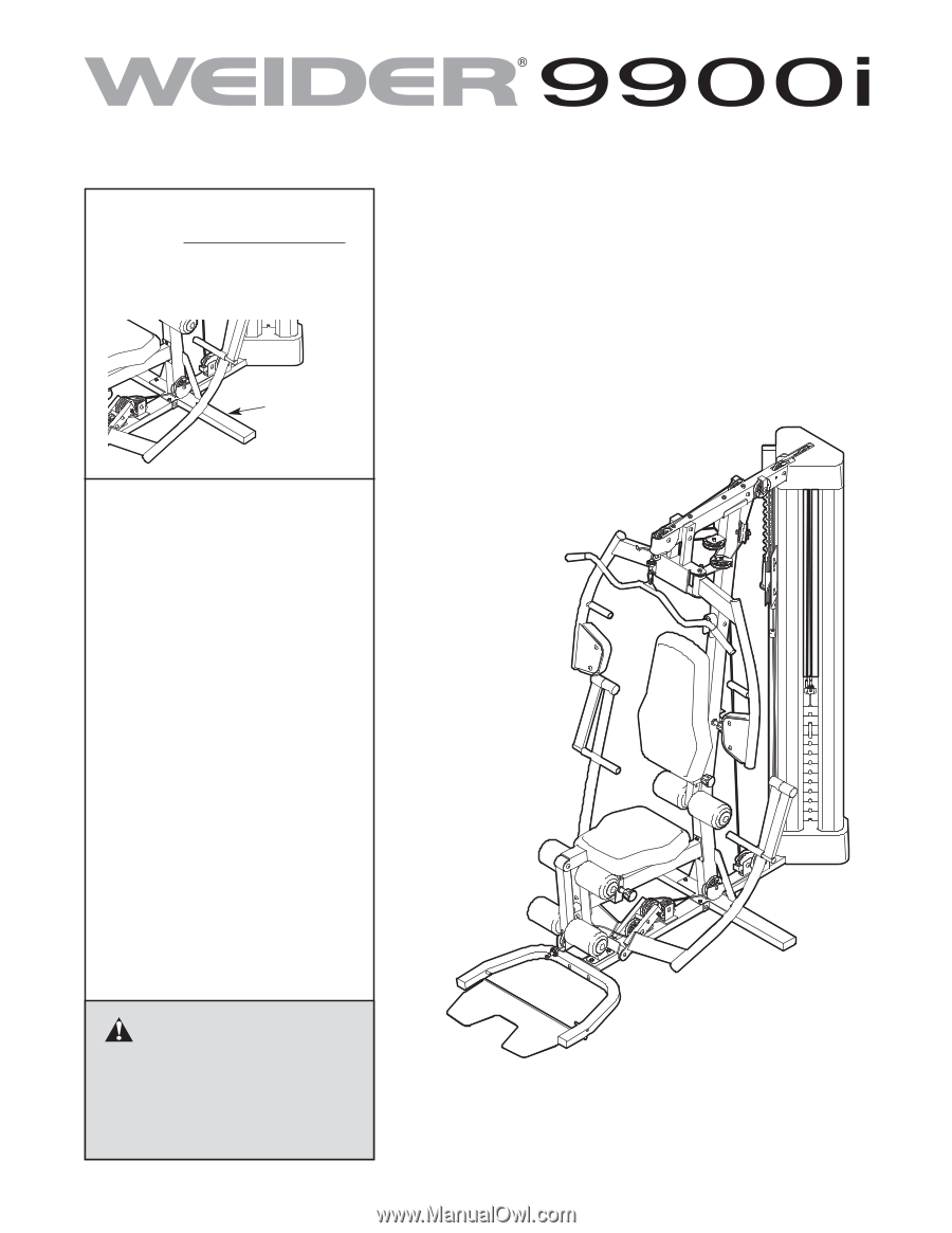
CAUTION
Read all precautions and instruc-
tions in this manual before using
this equipment. Keep this manual
for future reference.
Model No. WEEVSY49810.0
Serial No.
Write the serial number in the
space above for reference.
Serial Number
Decal
USERʼS MANUAL
www.iconeurope.com
QUESTIONS?
If you have questions, or if there are
missing parts, please contact us:
UK
Call: 08457 089 009
From Ireland: 053 92 36102
Website: www.iconsupport.eu
E-mail: [email protected]
Write:
ICON Health & Fitness, Ltd.
c/o HI Group PLC
Express Way
Whitwood, West Yorkshire
WF10 5QJ
UK
AUSTRALIA
Call: 1-800-237-173
E-mail: