Weider Pro 2000 Uk Manual
Weider Pro 2000 Manual
 |
View all Weider Pro 2000 manuals
Add to My Manuals
Save this manual to your list of manuals |
Weider Pro 2000 manual content summary:
- Weider Pro 2000 | Uk Manual - Page 1
Seat) QUESTIONS? As a manufacturer, we are committed to providing complete customer satisfaction. If you have questions, or if there are missing parts, all precautions and instructions in this manual before using this equipment. Save this manual for future reference. USER'S MANUAL Visit our website - Weider Pro 2000 | Uk Manual - Page 2
4 PART IDENTIFICATION CHART 5 ASSEMBLY 6 ADJUSTMENTS 17 WEIGHT RESISTANCE CHART 18 CABLE DIAGRAM 19 TROUBLESHOOTING AND MAINTENANCE 20 PART LIST 21 EXPLODED DRAWING 22 ORDERING REPLACEMENT PARTS Back Cover WARNING DECAL PLACEMENT The decal shown here has been placed on the weight system. If - Weider Pro 2000 | Uk Manual - Page 3
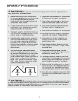
weight system is intended for home use only. Do not use the weight system in a commercial, rental, or institutional setting. 8. Always wear athletic shoes for foot protection when using the weight system. 9. Keep hands and feet away from moving parts. 10. The weight system is designed to support - Weider Pro 2000 | Uk Manual - Page 4
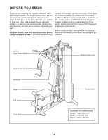
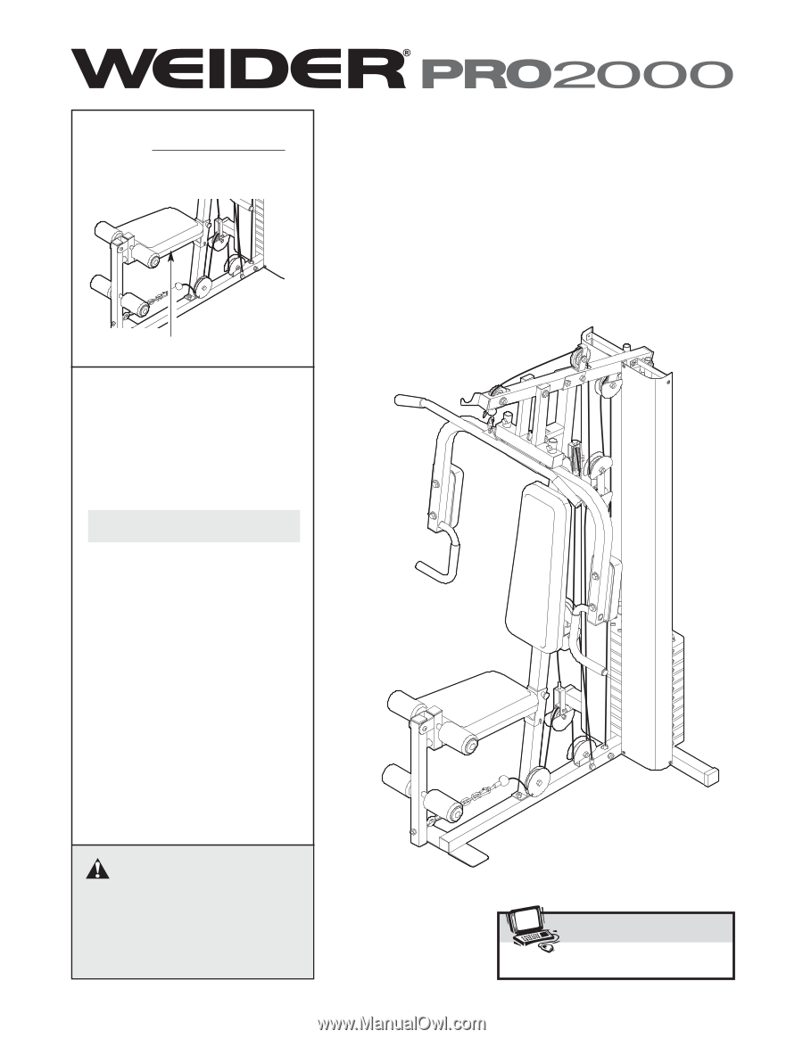
WEIDER® PRO 2000 weight system. The weight system offers a selection of weight stations review the drawing below and familiarize yourself with the parts that are labeled. Lat Bar High Pulley Station Butterfly Arm/Press Arm Backrest Seat Leg Lever Foot Plate Press Frame Lock Weight Stack ASSEMBLED - Weider Pro 2000 | Uk Manual - Page 5
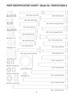
PART IDENTIFICATION CHART-Model No. WEEVSY2026.0 M4 x 12mm Selftapping Screw (56) M6 x 16mm Screw (40) M4 x 19mm Selftapping Screw (76) M6 Washer (73) M8 Washer (71) M6 x 63mm - Weider Pro 2000 | Uk Manual - Page 6
is completed. • Tighten all parts as you assemble them, unless instructed to do otherwise. • As you assemble the weight system, make sure all parts are oriented as shown in the drawings. • For help identifying small parts, use the PART IDENTIFICATION CHART. The following tools (not included - Weider Pro 2000 | Uk Manual - Page 7
the Press Frame Lock must pivot easily. 66 39 71 71 69 3 69 69 1 58 3. Set two Weight Bumpers (17) over the indicated 3 holes in the Stabilizer (2). Insert two Weight Guides (10) into the same holes. Make sure that the indicated holes are closer to the bottom of the Weight Guides. Secure the - Weider Pro 2000 | Uk Manual - Page 8
). Do not tighten the Nylon Locknuts yet. Attach the Top Frame (4) between the Weight Guides (10) with an M10 x 155mm Bolt (62), two M10 Washers (70), and an , 69) used in steps 2 and 5. 4 62 70 63 3 69 10 70 68 6. Attach the Seat Frame (8) to the Upright (3) with an M8 x 70mm Carriage Bolt (86 - Weider Pro 2000 | Uk Manual - Page 9
of the Bolt Set is inserted through both sides of the bracket on the Seat Frame. Do not overtighten the Bolt Set; the Leg Lever must pivot easily. Grease 8 81 9 81 8. Apply grease to an M10 x 125mm Bolt (64). Orient the Press Frame (5) with the bracket on the side shown. Attach the - Weider Pro 2000 | Uk Manual - Page 10
in the inset drawing. Press a 25mm Round Outer Cap (27) onto the post on the Left Arm (7). Repeat this step with the Right Arm (6). 10 6 Post 61 5 Bracket 61 72 27 29 72 7 CABLE ASSEMBLY 11 11. See the CABLE DIAGRAM on page 19 for proper cable routing. Locate the High Cable (50). Route the - Weider Pro 2000 | Uk Manual - Page 11
) and an M8 Nylon Locknut (69). Do not overtighten the Nylon Locknut; the Weight Tube must pivot easily in the Small "U"-bracket. 69 12 50 60 11 71 69 50 11 69 16. Locate the Press Cable (49). Slide the Cable 16 onto the hook on the Left Arm (7). Hook 49 17. Apply grease - Weider Pro 2000 | Uk Manual - Page 12
Bolt and an M10 Nylon Locknut (68). Do not overtighten the Nylon Locknut; the Pulley Arm must pivot easily. Wrap the Press Cable (49) over a 90mm Pulley (34). Attach the Pulley, a Cable Trap (36), an M10 Washer (70), and two Finger Guards (35) to the indicated side of a Pulley Arm (38) with an - Weider Pro 2000 | Uk Manual - Page 13
not com- pletely tighten the Nylon Locknut; it should be threaded onto the Cable so that two threads show past the Nylon Locknut, as shown in the inset drawing. 47 43 69 47 43 71 69 24. Locate the Low Cable (48). Attach the Cable 24 inside the Base (1) with an M10 x 65mm Bolt (55), two - Weider Pro 2000 | Uk Manual - Page 14
of holes in the "U"-bracket (43) with an M10 x 52mm Bolt (52) and an M10 Nylon Locknut (68). Make sure that the Cable Trap is oriented to hold the Cable in the groove of the Pulley. 34 48 53 35 1 35 68 52 43 35 35 68 36 34 48 28. Route - Weider Pro 2000 | Uk Manual - Page 15
SEAT ASSEMBLY 30. Attach the Backrest (18) to the Upright (3) with two M6 x 63mm Screws (67) and two M6 Washers (73). 30 18 Wide End 67 73 3 73 67 31. Attach the Seat (19), oriented as shown, to the Seat Frame (8) with four M6 x 16mm Screws (40). 31 19 Wide End 8 40 40 32. Slide - Weider Pro 2000 | Uk Manual - Page 16
the problem. IMPORTANT: If the cables are not properly routed, they may be damaged when heavy weight is used. See the CABLE DIAGRAM on page 19 of this manual for proper cable routing. If there is any slack in the cables, you will need to remove it by tightening the cables; see TROUBLESHOOTING AND - Weider Pro 2000 | Uk Manual - Page 17
section explains how to adjust the weight system. Refer to the accompanying exercise guide to see the correct form for each exercise. Make sure all parts are properly tightened each time you use the weight system. Replace any worn parts immediately. The weight system can be cleaned with a damp cloth - Weider Pro 2000 | Uk Manual - Page 18
at each exercise station. Weight resistance shown for the butterfly arm station is for each butterfly arm. Note: The actual resistance at each station may vary due to differences in individual weight plates as well as friction between the cables, pulleys, and weight guides. WEIGHT 1 PRESS ARM (lbs - Weider Pro 2000 | Uk Manual - Page 19
CABLE DIAGRAMS The cable diagrams below show the proper routing of the Short Cable (47), the Low Cable (48), the Press Cable (49), and the High Cable (50). Use the diagrams to make sure that the cables have been assembled correctly. If the cables have not been correctly routed, the weight system - Weider Pro 2000 | Uk Manual - Page 20
TROUBLESHOOTING AND MAINTENANCE TIGHTENING THE CABLES Woven cable, the type of cable used on the weight system, can stretch slightly when it is first used. If there is slack in the cables before resistance is felt, the cables should be tightened. Slack can be removed by moving a 90mm Pulley (34), - Weider Pro 2000 | Uk Manual - Page 21
PART LIST-Model No. WEEVSY2026.0 R0706A Key No. Qty. Description Key No. Qty. Description 1 1 Base 2 1 Stabilizer 3 1 Upright 4 1 Top Frame 5 1 Press Frame 6 1 Right Arm 7 1 Left Arm 8 1 Seat Frame 9 1 Leg Lever 10 2 Weight Guide 11 1 Small "U"-bracket 12 1 - Weider Pro 2000 | Uk Manual - Page 22
EXPLODED DRAWING A-Model No. WEEVSY2026.0 R0706A 70 25 64 27 29 26 70 68 27 49 5 28 61 29 26 6 72 28 72 73 49 24 61 7 65 73 74 20 24 23 73 84 63 55 37 70 50 53 34 36 34 52 68 4 53 69 85 26 68 37 70 68 68 35 34 35 35 34 35 20 65 78 73 24 74 78 22 21 45 86 24 - Weider Pro 2000 | Uk Manual - Page 23
51 48 77 55 51 56 70 35 34 68 35 53 68 68 68 70 1 68 47 57 83 58 23 77 41 2 33 10 79 77 80 56 50 71 69 69 87 15 60 11 12 13 16 77 56 17 37 70 57 70 41 59 - Weider Pro 2000 | Uk Manual - Page 24
the UK: 0 (044) 113 387 7133 Fax: 0 (044) 113 387 7125 Please provide the following information when ordering replacement parts: • the MODEL NUMBER of the product (WEEVSY2026.0) • the NAME of the product (WEIDER PRO 2000 weight system) • the SERIAL NUMBER of the product (see the front cover of this
-
 1
1 -
 2
2 -
 3
3 -
 4
4 -
 5
5 -
 6
6 -
 7
7 -
8
-
9
-
10
-
11
-
12
-
13
-
14
-
15
-
16
-
17
-
18
-
19
-
20
-
21
-
22
-
23
-
24
 |
 |
USER'S MANUAL
CAUTION
Read all precautions and instruc-
tions in this manual before using
this equipment. Save this manual
for future reference.
Model No. WEEVSY2026.0
Serial No.
Write the serial number in the
space above for future reference.
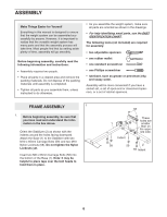
Serial Number Decal (Under Seat)
QUESTIONS?
As a manufacturer, we are com-
mitted to providing complete
customer satisfaction. If you have
questions, or if there are missing
parts, please call:
Or write:
ICON Health & Fitness, Ltd.
Unit 4
Revie Road Industrial Estate
Revie Road
Beeston
Leeds, LS118JG
UK
email: [email protected]
www.iconeurope.com
Visit our website at
08457 089 009