Weider Pro 3200 English Manual
Weider Pro 3200 Manual
 |
View all Weider Pro 3200 manuals
Add to My Manuals
Save this manual to your list of manuals |
Weider Pro 3200 manual content summary:
- Weider Pro 3200 | English Manual - Page 1
or if there are missing parts, we will guarantee complete satisfaction free of charge to you. CUSTOMER HOT LINE: 1-800-999-3756 Mon.-Fri., 6 a.m.-6 p.m. MST CAUTION Read all precautions and instructions in this manual before using this equipment. Save this manual for future reference. USER'S MANUAL - Weider Pro 3200 | English Manual - Page 2
4 ASSEMBLY 5 ADJUSTMENTS 20 WEIGHT RESISTANCE CHART 23 CABLE DIAGRAM 24 EXERCISE GUIDELINES 26 ORDERING REPLACEMENT PARTS Back Cover FULL 90 DAY WARRANTY Back Cover Note: A PART IDENTIFICATION CHART and a PART LIST/EXPLODED DRAWING are attached in the center of this manual. Remove the PART - Weider Pro 3200 | English Manual - Page 3
It is the responsibility of the owner to ensure that all users of the weight system are adequately informed of all precautions. 12. Always stand on the foot plate when performing an exercise that could cause the weight system to tip. 3. The weight system is intended for home use only. Do not use - Weider Pro 3200 | English Manual - Page 4
versatile WEIDER® PRO 3200 weight system. The PRO 3200 weight system offers a selection of weight stations weight system (see the front cover of this manual). Before reading further, please review the drawing below and familiarize yourself with the parts that are labeled. ASSEMBLED DIMENSIONS - Weider Pro 3200 | English Manual - Page 5
packing materials until assembly is completed. • Tighten all parts as you assemble them, unless instructed to do otherwise. • As you assemble the weight system, make sure all parts are oriented as shown in the drawings. • For help identifying small parts, use the PART IDENTIFICATION CHART. An Allen - Weider Pro 3200 | English Manual - Page 6
3. Attach the Base Plate (37) to the Left Base (2) with an M10 x 135mm Bolt (58) and an M10 Nylon Locknut (70). Be sure that the textured side is on top. Attach the Left Upright (7) to the Left Base (2) with the two indicated M10 x 65mm Carriage Bolts (57) and two M10 Nylon Locknuts (70). Attach the - Weider Pro 3200 | English Manual - Page 7
M10 Nylon Locknuts (70). Do not tighten the M10 Nylon Locknuts (70) yet. 7. Set two Weight Bumpers (83) over the indicated holes in the Center Base (67). Insert the two Weight Guides (20) into the holes. Attach the Weight Guides to the Center Base with two M10 x 65mm Bolts (63), four M10 Washers (75 - Weider Pro 3200 | English Manual - Page 8
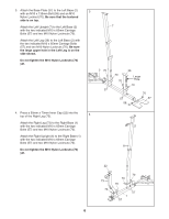
Top Weight onto the Weight Guides (20), with the pin groove on the bottom. 20 74 Pin Groove Lubricate Holes 82 32 72 9. Press two 50mm x 70mm Inner Caps (22) into the ends of the Left Top Frame (3). Attach the Left Top Frame (3) to the Left Upright (7) with two M10 x 90mm Bolts (59), a Support - Weider Pro 3200 | English Manual - Page 9
Center Top Frame (14). Slide the Center Top Frame onto the Weight Guides (20). Attach the Center Top Frame (14) to the Right Top in steps 3-11. 11 70 44 70 14 81 75 70 8 70 75 81 75 20 3 ARM ASSEMBLY 12 8 12. Press a 38mm Square Inner Cap (41) into the Right Upright (6). Press a 50mm x - Weider Pro 3200 | English Manual - Page 10
14. Lubricate an M10 x 80mm Button Head Bolt (97) and both sides of two Plastic Washers (55) with grease. Attach the Right Butterfly Arm (11) to the Butterfly Frame (9) with the Bolt, the two Plastic 14 Lubricate 97 Welded Bushing 55 54 Washers, two Butterfly Caps (54), and an M10 11 Nylon - Weider Pro 3200 | English Manual - Page 11
assembling the cables, do not overtighten the locknuts attaching the pulleys; the pulleys must be able to turn freely. Refer to the CABLE DIAGRAMS and the CABLE ID CHART following drawings are shown from 20 the left side of the weight system, with the Left Top Frame (3) removed for clarity. Wrap - Weider Pro 3200 | English Manual - Page 12
in the inset drawing. Attach the Small "U"-Bracket (79) to the Weight Tube (82) with an M8 x 45mm Bolt (69) and an M8 Nylon Locknut (71). Do not overtighten the Locknut; the Weight Tube should be able to pivot in the "U"-Bracket. 22 79 69 66 45 71 - Weider Pro 3200 | English Manual - Page 13
25. Route the Leg Press Cable (95) through the Left 25 Leg (36) and the Left Upright (7) as shown. Wrap the Cable around a 90mm Pulley (38). Attach the Pulley inside the Upright with an M10 x 70mm Bolt (81), two M10 Washers (75), two 13mm Spacers (34), and an M10 Nylon Locknut (70). 26. Wrap - Weider Pro 3200 | English Manual - Page 14
29. Wrap the Butterfly Cable (46) around a "V"-Pulley 29 (39). Attach the Pulley and a Long Cable Trap (40) to the bracket on the Right Upright (6) with an M10 x 60mm Bolt (65) and an M10 Nylon Locknut (70). Be sure the Cable Trap is turned to hold the Cable in the groove of the Pulley. 6 70 - Weider Pro 3200 | English Manual - Page 15
33. Locate the Leg Lever Cable (96). Route the eyelet end of the Cable through the Right Leg (73) and attach it to the Leg Lever (4) with an M10 x 25mm Shoulder Bolt (99) and an M10 Nylon Locknut (70). 33 4 70 73 34. Attach a 90mm Pulley (38) inside the Right Leg (73) with an M10 x 70mm Bolt (81 - Weider Pro 3200 | English Manual - Page 16
37. Attach the end of the Leg Lever Cable (96) to the 37 other "U"-Bracket (85) with an M8 Washer (26) and an M8 Nylon Locknut (71). Note: Do not completely tighten the Nylon Locknut; it should be threaded only two turns onto the end of the Cable, as shown in the inset draw- ing. 38. Locate - Weider Pro 3200 | English Manual - Page 17
41. Wrap the Low Cable (47) around a 90mm Pulley 41 (38). Attach the Pulley to the indicated bracket on the Left Base (2) with an M10 x 45mm Bolt (66) and an M10 Nylon Locknut (70). 42. Wrap the Low Cable (47) around a 90mm Pulley 42 (38). Attach the Pulley to the indicated bracket on the - Weider Pro 3200 | English Manual - Page 18
45. Wrap the Low Cable (47) around a 90mm Pulley 45 (38). Attach the Pulley and a Cable Trap (91) to the indicated bracket on the Right Base (1) with an M10 x 45mm Bolt (66) and an M10 Nylon Locknut (70). Be sure the Cable Trap is turned to hold the Cable in the groove of the Pulley. 70 91 38 - Weider Pro 3200 | English Manual - Page 19
SEAT ASSEMBLY 49. Press two 20mm x 40mm Inner Caps (104) and a 25mm x 40mm Inner Cap (105) into an Adjustable Seat Frame (100). Attach a Seat (16) to an - Weider Pro 3200 | English Manual - Page 20
get the most benefit from your exercise program. Also, refer to the accompanying exercise guide to see the correct form for each exercise. Make sure all parts are properly tightened each time the weight system is used. Replace any worn parts immediately. The weight system can be cleaned with a damp - Weider Pro 3200 | English Manual - Page 21
: Due to the cables and pulleys, the actual amount of resistance at each exercise station may vary from the weight setting. Use the WEIGHT RESISTANCE CHART on page 23 to find the actual amount of resistance at each weight station. CONVERTING THE BUTTERFLY ARMS To use the Butterfly Arms (10, 11) as - Weider Pro 3200 | English Manual - Page 22
TIGHTENING THE CABLES Woven cable, the type of cable used on the weight system, can stretch slightly when it is first used. If there is slack in the cables before resistance is felt, the cables should be tightened. See - Weider Pro 3200 | English Manual - Page 23
WEIGHT RESISTANCE CHART The chart below shows the approximate weight resistance at each exercise station. "Top" refers to the 6-pound top weight. The other numbers refer to the 12.5-pound weight plates. Weight weight plates as well as friction between the cables, pulleys, and weight guides. WEIGHT - Weider Pro 3200 | English Manual - Page 24
Leg Lever Cable (96). Use the diagrams to make sure that the cables and the cable traps have been assembled correctly. If the cables have not been correctly routed, the weight system will not function properly and damage may occur. The numbers show the correct route for each cable. Make sure that - Weider Pro 3200 | English Manual - Page 25
4 4 Leg Lever Cable (96) 5 5 3 12 CABLE ID CHART - (46) 47 3/7" - (96) 95 1/2" - (95) 148 1/4" - (47) 276 3/4" - (45) 116 3/4" Leg Press Cable (95) 3 2 1 25 - Weider Pro 3200 | English Manual - Page 26
the appropriate parts of the body. Exercising in an uncontrolled manner will leave you feeling exhausted. On the exercise guide accompanying this manual you will find photographs showing the correct form for several exercises, and a list of the muscles affected. Refer to the muscle chart on page - Weider Pro 3200 | English Manual - Page 27
of sets and repetitions completed. Record your weight and key body measurements at the end of every month. Remember, the key to achieving the greatest results is to make exercise a regular and enjoyable part of your everyday life. MUSCLE CHART A. Sternomastoid (neck) B. Pectoralis Major (chest - Weider Pro 3200 | English Manual - Page 28
PART IDENTIFICATION CHART-Model No. WESY29521 R1002B M10 Washer (75) M8 Washer (26) M6 Washer (35) M5 Washer (50) M10 Nylon Locknut (70) M8 Nylon Locknut (71) 25mm - Weider Pro 3200 | English Manual - Page 29
M10 x 50mm Bolt (62) M10 x 45mm Bolt (66) M8 x 45mm Bolt (69) M6 x 33mm Screw (90) M10 x 25mm Shoulder Bolt (99) M8 x 16mm Shoulder Bolt (78) M4 x 20mm Self-tapping Screw (77) M8 x 16mm Bolt (64) M6 x 16mm Bolt (13) M4 x 9.5mm Self-tapping Screw (68) M10 x 60mm Bolt (65) M8 x 65mm Bolt (89) M10 x - Weider Pro 3200 | English Manual - Page 30
Center Top Frame Backrest Seat Long Pad Tube Foam Pad Large Foam Pad Weight Guide Support Plate 50mm x 70mm Inner Cap 40mm x 50mm Inner Cap 25mm Round 40mm Inner Cap User's Manual Exercise Guide Allen Wrench Grease Packet Note: "#" indicates a non-illustrated part. Specifications are subject to - Weider Pro 3200 | English Manual - Page 31
EXPLODED DRAWING-Model No. WESY29521 70 38 70 62 11 26 64 70 26 64 24 78 46 71 48 71 62 46 78 48 23 70 10 19 66 70 14 59 81 21 75 8 22 70 97 70 54 55 22 53 9 61 68 97 54 40 70 66 65 39 44 70 70 84 41 75 38 47 92 104 13 101 38 70 39 40 70 65 75 70 20 70 70 44 20 38 91 75 - Weider Pro 3200 | English Manual - Page 32
(WEIDER® PRO 3200 weight system) 3. The SERIAL NUMBER of the product (see the front cover of this manual) 4. The KEY NUMBER and DESCRIPTION of the part(s) (see the PART LIST in the center of this manual) LIMITED WARRANTY ICON Health & Fitness, Inc. (ICON), warrants this product to be free from
-
 1
1 -
 2
2 -
 3
3 -
 4
4 -
 5
5 -
 6
6 -
 7
7 -
8
-
9
-
10
-
11
-
12
-
13
-
14
-
15
-
16
-
17
-
18
-
19
-
20
-
21
-
22
-
23
-
24
-
25
-
26
-
27
-
28
-
29
-
30
-
31
-
32
 |
 |

USER'S MANUAL
CAUTION
Read all precautions and instruc-
tions in this manual before using
this equipment. Save this manual
for future reference.
Model No. WESY29521
Serial No.
Write the serial number in the
space above for reference.
Serial Number Decal (under seat)
Visit our website at
www.weiderfitness.com
new products, prizes,
fitness tips, and much more!
QUESTIONS?
As a manufacturer, we are
committed to providing com-
plete customer satisfaction. If
you have questions, or if there
are missing parts, we will guar-
antee complete satisfaction
through direct assistance from
our factory.
TO AVOID DELAYS, PLEASE
CALL DIRECT TO OUR TOLL-
FREE CUSTOMER HOT LINE.
The trained technicians on our
customer hot line will provide
immediate assistance, free of
charge to you.
CUSTOMER HOT LINE:
1-800-999-3756
Mon.–Fri., 6 a.m.–6 p.m. MST