Weider Pro 5500 User Manual - Page 12
Arm Assembly
 |
View all Weider Pro 5500 manuals
Add to My Manuals
Save this manual to your list of manuals |
Page 12 highlights
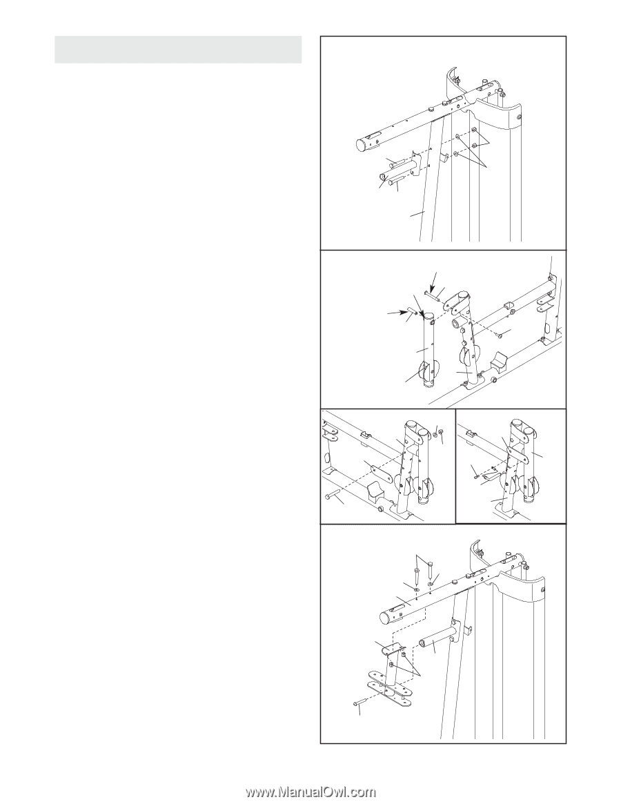
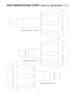
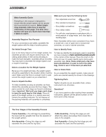
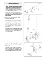
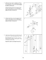
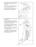
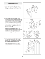
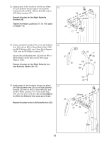
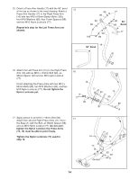
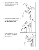
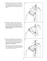
Arm Assembly 9 9. Attach the Butterfly Frame Brace (6) to the Upright (2) with two M8 x 80mm Bolts (100), two M8 Washers (103), and two M8 Nylon Locknuts (78). Do not tighten the Nylon Locknuts yet. 78 100 103 6 100 2 10. Apply grease in the locations shown. Insert a 56.5mm Spacer (69) the indicated hole in the Leg Lever (12). Attach the Leg Lever to the Front Leg (10) with an M10 x 61mm Bolt Set (116). Make sure the indicated rod is oriented as shown. See the left inset drawing. Attach the Lock Plate (14) to the Front Leg (10) with the M8 x 69mm Shoulder Bolt (87), an M8 Washer (103), and an M8 Nylon Locknut (78). See the right inset drawing. Insert the Lock Plate Pin (95) through the Lock Plate (14) and the Leg Lever (12). Attach the tether on the Lock Plate Pin to the Front Leg (10) with an M4 x 12mm Self-tapping Screw (102). 11. Attach the Butterfly Frame (5) to the Top Frame (4) with two M8 x 80mm Bolts (100), two M8 Washers (103), and two M8 Nylon Locknuts (78). Do not tighten the Nylon Locknuts yet. Attach the Butterfly Frame (5) to the Butterfly Frame Brace (6) with an M10 x 75mm Button Screw (118). 10 Grease 116 Hole Grease 69 116 12 10 Rod 103 10 14 78 14 102 12 87 11 95 10 100 103 103 4 5 6 78 118 12
-
 1
1 -
2
-
3
-
4
-
5
-
6
-
 7
7 -
 8
8 -
 9
9 -
 10
10 -
 11
11 -
 12
12 -
 13
13 -
 14
14 -
 15
15 -
 16
16 -
 17
17 -
18
-
19
-
20
-
21
-
22
-
23
-
24
-
25
-
26
-
27
-
28
-
29
-
30
-
31
-
32
-
33
-
34
-
35
-
36
 |
 |