Weider Pro 7500 Uk Manual
Weider Pro 7500 Manual
 |
View all Weider Pro 7500 manuals
Add to My Manuals
Save this manual to your list of manuals |
Weider Pro 7500 manual content summary:
- Weider Pro 7500 | Uk Manual - Page 1
parts, please call: 08457 089 009 Or write: ICON Health & Fitness, Ltd. Unit 4 Revie Road Industrial Estate Revie Road, Beeston Leeds, LS11 8JG UK Fax: 0 (44) 113 3877125 E-mail: [email protected] CAUTION Read all precautions and instructions in this manual before using this equipment. Save this - Weider Pro 7500 | Uk Manual - Page 2
7 ADJUSTMENTS 28 WEIGHT RESISTANCE CHART 31 CABLE DIAGRAM 32 MAINTENANCE 34 EXERCISE GUIDELINES 35 PART LIST 39 EXPLODED DRAWING 41 ORDERING REPLACEMENT PARTS Back Cover WEIDER is a registered trademark of ICON IP, Inc. 2 - Weider Pro 7500 | Uk Manual - Page 3
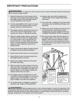
system is designed to support a maximum user weight of 135 kg (295 lbs). WARNING: Before beginning this or any exercise program, consult your physician. This is especially important for persons over the age of 35 or persons with pre-existing health problems. Read all instructions before using. ICON - Weider Pro 7500 | Uk Manual - Page 4
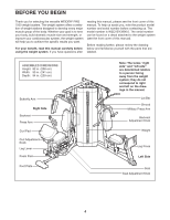
for selecting the versatile WEIDER® PRO 7500 weight system. The weight system offers a selection attached to the weight system (see the front cover of this manual). Before reading further, please review the drawing below and familiarize yourself with the parts that are labeled. ASSEMBLED DIMENSIONS - Weider Pro 7500 | Uk Manual - Page 5
, from the PART LIST on pages 39 and 40. Note: Some small parts may have been pre-attached. If a part is not in the parts bag, check to see if it has been pre-attached. M8 Nylon Locknut (78) M10 Nylon Locknut (77) M12 Nut (112) M4 Washer (104) M6 Washer (114 - Weider Pro 7500 | Uk Manual - Page 6
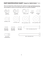
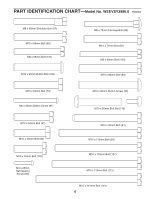
PART IDENTIFICATION CHART-Model No. WEEVSY3996.0 R0806A M8 x 69mm Shoulder Bolt (87) M10 x 68mm Bolt (85) M8 x 65mm Bolt (101) M10 x 65mm Button Bolt (106) M8 x 75mm Carriage Bolt (83) M10 x 75mm Bolt (82) M8 x 80mm Bolt (100) M10 x 82mm Bolt (84) M10 x 63mm Bolt (79) M6 x 60mm Button Screw (91) - Weider Pro 7500 | Uk Manual - Page 7
PART IDENTIFICATION CHART in the center of this manual. Place the chart on the floor and use attached. How to Orient Parts As you assemble the weight system, make sure all parts are oriented exactly as shown in the drawings. Tightening Parts Tighten all parts as you assemble them, unless instructed - Weider Pro 7500 | Uk Manual - Page 8
Apply a portion of the included grease to an M10 x 141mm Bolt (141). Attach the Foot Plate (146) to the Right Base (1) with the Bolt and an 78). Do not tighten the Nylon Locknuts yet. 78 103 100 103 78 1 119 4. Attach the Bottom Center Base (147) to the Right and Left Bases (1, 119) with four - Weider Pro 7500 | Uk Manual - Page 9
Bolts (83). Do not tighten the Nylon Locknuts yet. 6. Orient the Rear Upright (121) so that the top 6 bracket slopes toward the Left Upright (120). Attach the Rear Upright to the Left Base (119) with two M8 Nylon Locknuts (78) and the indi- cated M8 x 75mm Carriage Bolts (83). Do not - Weider Pro 7500 | Uk Manual - Page 10
). Do not tighten the Nylon Locknuts yet. 4 78 103 100 100 103 126 78 78 78 121 120 9. Orient the Weight Guides (18) with the indicated 9 holes toward the floor. Attach a Weight Guide to the Bottom Center Base (147) with an M10 x 82mm Bolt (84), two M10 Washers (80), two 20mm Steel Spacers - Weider Pro 7500 | Uk Manual - Page 11
) with four M10 x 82mm Bolts (84), two Top Frame Plates (137), and two M10 Nylon Locknuts (77). Do not tighten the Nylon Locknuts yet. Attach the Weight Guides (18) to the Top Center Frame (148) with two M10 x 90mm Bolts (81), four M10 Washers (80), and two M10 Nylon Locknuts (77). Do - Weider Pro 7500 | Uk Manual - Page 12
Do not tighten the Nylon Locknuts yet. 75 104 110 10 78 78 83 1 13. Attach the Right Frame (9) to the Front Leg (10) 13 and the Right Upright (2) with Nylon Locknuts yet. 9 78 78 10 78 78 2 103 100 101 103 14. Attach the Left Frame (122) to the Left Base 14 (119) and the Left Upright - Weider Pro 7500 | Uk Manual - Page 13
Right Upright (2) with two M8 x 80mm Bolts (100), two M8 Washers (103), and two M8 Nylon Locknuts (78). Do not tighten the Nylon Locknuts yet. Attach the Butterfly Frame (5) to the Right Top Frame (4) and the Butterfly Frame Brace (6) with two M8 x 80mm Bolts (100), an M10 x 75mm Button Screw (118 - Weider Pro 7500 | Uk Manual - Page 14
68mm Bolt (85). Then, insert the Bushing into the Military Press Frame (127). Attach the Military Press Frame inside the Left Upright (120) with the Bolt (85) and 85 120 19. Apply grease to an M10 x 40mm Bolt (142). 19 Attach the Military Press Arm (128) to the Military Press Frame (127) with - Weider Pro 7500 | Uk Manual - Page 15
a 22 57mm Spacer (69) into the indicated hole in the Leg Lever (12). Attach the Leg Lever to the Front Leg (10) with an M10 x 60mm Bolt Set Leg. Make sure the indicated rod is oriented as shown. See the left inset drawing. Attach the Lock Plate (14) to the Front Leg (10) with an M8 x 69mm - Weider Pro 7500 | Uk Manual - Page 16
Butterfly Cable (50). Grease an M8 x 22mm Shoulder Bolt (90). Attach the Cable to the Left Butterfly Bracket (28) with the Shoulder Bolt Grease Flat Edge 26. Wrap the Butterfly Cable (50) over a "V"-pulley 26 (47). Attach the "V"-pulley, a Long Cable Trap (57), an M10 Washer (80), and two Guards - Weider Pro 7500 | Uk Manual - Page 17
55 55 61 28. Wrap the Butterfly Cable (50) over a "V"-pulley 28 (47). Attach the "V"-pulley, a Long Cable Trap (57), an M10 Washer (80), and two Guards 54 2 77 29. Grease an M8 x 22mm Shoulder Bolt (90). 29 Attach the Butterfly Cable (50) to the Right Butterfly Bracket (29) with the Shoulder - Weider Pro 7500 | Uk Manual - Page 18
over a 90mm Pulley 31 (48) and down through the Left Top Frame (126). Attach the Pulley inside the Left Top Frame with an M10 x 82mm Bolt (84), two through the Left 33 Top Frame (126) and over a 90mm Pulley (48). Attach the Pulley inside the Left Top Frame with an M10 x 82mm Bolt (84), two - Weider Pro 7500 | Uk Manual - Page 19
oriented as shown. 35. Wrap the Lat Cable (49) over a 90mm Pulley (48). Attach the Pulley to the Left Top Frame 35 (126) with an M10 x 45mm Bolt (86 as shown. 37. Wrap the Lat Cable (49) over a 90mm Pulley 37 (48). Attach the Pulley to the Right Top Frame (4) with an M10 x 45mm Bolt (86) and - Weider Pro 7500 | Uk Manual - Page 20
M12 Large Washer (98). 49 112 20 98 40. Identify the Press Cable (133). Attach the 40 Cable to the Left Frame (122) with an M10 x 82mm Bolt (84), 84 77 80 133 41. Wrap the Press Cable (133) over a 90mm Pulley (48). Attach the Pulley and a Cable Trap (56) to the Leg Press Frame (123) with an - Weider Pro 7500 | Uk Manual - Page 21
Bar 2 Leg (10), under the indicated bar, and through the Right Upright (2). Insert a 90mm Pulley (48) into the Leg Lever (12) from the indicated direction. Attach the Pulley to the Leg Lever with an M10 x 68mm Bolt (85), two M10 Washers (80), two 13mm Steel Spacers (109), and an M10 Nylon - Weider Pro 7500 | Uk Manual - Page 22
on the Right Base (1). Then, wrap 47 the Cable under a 90mm Pulley (48). Attach the Pulley to the Right Base with an M10 x 50mm Bolt (97), two Half as shown. 49. Wrap the Leg Lever Cable (51) under a 90mm Pulley (48). Attach the Pulley to the Right Base 49 (1) with an M10 x 50mm Bolt (97), - Weider Pro 7500 | Uk Manual - Page 23
as shown. 51. Wrap the Leg Lever Cable (51) over a 90mm Pulley (48). Attach the Pulley to the Double "U" 51 -bracket (61) with an M10 x 50mm Bolt ( 77 53. Wrap the Leg Lever Cable (51) under a 90mm 53 Pulley (48). Attach the Pulley and a Cable Trap (56) to the Right Press Arm (16) with an - Weider Pro 7500 | Uk Manual - Page 24
the Right Upright (2) with the M10 x 120mm Bolt (115), an M10 Washer (80), a 7mm Spacer (111), and the M10 Nylon Locknut. Seat Assembly 57 57. Attach a Backrest (31) to the Right Backrest Frame (7) with two M6 x 16mm Screws (88), an M6 x 32mm Screw (89), and an M6 Washer (114). Insert the - Weider Pro 7500 | Uk Manual - Page 25
the Adjustment Knob passes through one of the holes in the Right Seat Frame. 59. Attach the Left Seat (129) to the Left Seat 59 Frame (125) with two M6 Frame. 32 8 88 9 89 114 52 129 114 145 53 125 88 122 60. Attach the Right Butterfly Pad (35) to the Right Butterfly Arm (26) with two M6 - Weider Pro 7500 | Uk Manual - Page 26
M4 x 12mm Self-tapping 62 Screws (102). 102 30 5 102 63. Attach a Shroud (21) to the Top Center Frame and Bottom Center Base (148 (84) securing the Top Center Frame and the Weight Guides (18). Attach the other Shroud (21) in the same manner. Attach the Shroud Covers (23) to the Shrouds (21) - Weider Pro 7500 | Uk Manual - Page 27
ADJUSTMENTS, beginning on the following page. Before using the weight system, pull each cable a few times to make sure that the cables move smoothly over the pulleys. If one of the cables does not move smoothly, find and correct the problem. IMPORTANT: If the cables are not properly installed, they - Weider Pro 7500 | Uk Manual - Page 28
Pin is touching the Weights, and turn the bent end upward. Note: The weight system works best when at least two Weights are used. 19 70 ATTACHING THE ACCESSORIES To attach the Lat Bar (63) to the Lat Cable (49), attach a Weight Clip (66) to the Lat Cable and the Lat Bar. Note: For some - Weider Pro 7500 | Uk Manual - Page 29
10 2 31 53 LOCKING THE WEIGHT STACK To lock the weight stack, insert the Locking Pin (72) through one of the holes in the Weight Guides (18) and secure the Locking Pin with the Lock (73). 18 72 73 29 - Weider Pro 7500 | Uk Manual - Page 30
LOCKING THE LEG LEVER To lock or unlock the Leg Lever (12), remove the Lock Plate Pin (95) from the Lock Plate (14). Move the Lock Plate to either the position shown on the Front Leg (10), or the indicated hole in the Leg Lever. Insert the Lock Pin back through the Lock Plate. 10 14 95 12 Hole 30 - Weider Pro 7500 | Uk Manual - Page 31
resistance at each station may vary due to differences in individual weight plates as well as friction between the cables, pulleys, and weight guides. The maximum number of plates when performing exercises with the Butterfly Arms (25, 26) is 10. WEIGHT 1 HIGH PULLEY (lbs.) BUTTERFLY ARM (lbs - Weider Pro 7500 | Uk Manual - Page 32
the diagram to make sure that the cables and the cable traps have been assembled correctly. If a cable has not been correctly routed, the weight system will not function properly and damage may occur. The numbers show the correct route for the cables. Make sure that the cable traps do not - Weider Pro 7500 | Uk Manual - Page 33
4 Leg Lever Cable (51) Length: 265in. (672cm) 7 8 5 6 9 10 3 12 11 33 - Weider Pro 7500 | Uk Manual - Page 34
. TIGHTENING THE CABLES Woven cable, the type of cable used on the weight system, can stretch slightly when it is first used. If there is slack in (60). Reattach the Pulley, Cable Trap, and Half Guards to the next closer hole to the cen- ter of the Pulley Plates. Make sure that the manual. 34 - Weider Pro 7500 | Uk Manual - Page 35
20 to 30 minutes of aerobic exercise, such as running on a treadmill or riding on an elliptical exerciser or exercise cycle, on Tuesday and Thursday manner will leave you feeling exhausted. On the exercise guide accompanying this manual you will find photographs showing the correct form for several - Weider Pro 7500 | Uk Manual - Page 36
Rest for a short period of time after each set. The ideal resting periods follow: • Rest for three minutes after each set for a muscle building workout. • Rest for one minute after each set for a toning work- out. • Rest for 30 seconds after each set for a weight loss workout. Plan to spend the - Weider Pro 7500 | Uk Manual - Page 37
MONDAY Date: // EXERCISE WEIGHT SETS REPS TUESDAY Date: // WEDNESDAY Date: // AEROBIC EXERCISE EXERCISE WEIGHT SETS REPS THURSDAY Date: // FRIDAY Date: // AEROBIC EXERCISE EXERCISE WEIGHT SETS REPS Make photocopies of this page for scheduling and recording your workouts. 37 - Weider Pro 7500 | Uk Manual - Page 38
MONDAY Date: // EXERCISE WEIGHT SETS REPS TUESDAY Date: // WEDNESDAY Date: // AEROBIC EXERCISE EXERCISE WEIGHT SETS REPS THURSDAY Date: // FRIDAY Date: // AEROBIC EXERCISE EXERCISE WEIGHT SETS REPS Make photocopies of this page for scheduling and recording your workouts. 38 - Weider Pro 7500 | Uk Manual - Page 39
1 Curl Post 12 1 Leg Lever 13 2 Pad Tube 14 1 Lock Plate 15 1 Left Press Arm 16 1 Right Press Arm 17 2 Press Arm Handle 18 2 Weight Guide 19 15 Weight 20 1 Weight Tube 21 2 Shroud 22 2 Butterfly Handgrip 23 2 Shroud Cover 24 1 Upright Cover 25 1 Left Butterfly Arm 26 1 Right Butterfly Arm - Weider Pro 7500 | Uk Manual - Page 40
Inner Cap M6 x 45mm Screw Foot Plate Bottom Center Base Top Center Frame Press Arm Handgrip 34mm Round Inner Cap "U"-bracket User's Manual Exercise Guide Hex Key Grease Packet Note: "#" indicates a non-illustrated part. Specifications are subject to change without notice. See the back cover of this - Weider Pro 7500 | Uk Manual - Page 41
EXPLODED DRAWING-Model No. WEEVSY3996.0 81 80 81 77 77 110 110 110 104 104 104 48 86 23 148 49 112 77 98 19 102 102 R0806A 20 21 76 21 19 70 71 71 80 80 110 77 77 80 104 102 102 110 104 23 40 99 77 18 99 80 149 80 99 84 80 108 78 147 108 80 77 106 72 73 - Weider Pro 7500 | Uk Manual - Page 42
EXPLODED DRAWING-Model No. WEEVSY3996.0 R0806A 103 100 84 100 100 103 84 38 103 137 48 80 67 48 126 6780 84 80 67 77 86 77 48 78 67 77 80 38 78 48 56 55 77 151 97 55 78 103 133 64 49 64 63 55 77 56 48 55 78 102 88 41 55 6056 97 48 60 55 24 42 96 3 94 104 89 114 31 - Weider Pro 7500 | Uk Manual - Page 43
EXPLODED DRAWING-Model No. WEEVSY3996.0 R0806A 45 45 74 27 109 106 109 77 74 74 90 50 46 84 100 100 103 78 137 114 80 80 91 43 105 26 92 82 77 78 29 44 46 35 74 90 50 74 46 77 28 45 74 82 78 30 103 38 84 102 118 4 5 78 84 77 86 48 79 54 57 4780 78 77 78 117 66 - Weider Pro 7500 | Uk Manual - Page 44
NUMBER of the product (WEEVSY3996.0) • the NAME of the product (WEIDER PRO 7500 weight system) • the SERIAL NUMBER of the product (see the front cover of this manual) • the KEY NUMBER and DESCRIPTION of the part(s) (see pages 39-43) Part No. 242678 R0806A Printed in China © 2006 ICON IP, Inc.
-
 1
1 -
 2
2 -
 3
3 -
 4
4 -
 5
5 -
 6
6 -
 7
7 -
8
-
9
-
10
-
11
-
12
-
13
-
14
-
15
-
16
-
17
-
18
-
19
-
20
-
21
-
22
-
23
-
24
-
25
-
26
-
27
-
28
-
29
-
30
-
31
-
32
-
33
-
34
-
35
-
36
-
37
-
38
-
39
-
40
-
41
-
42
-
43
-
44
 |
 |

CAUTION
Read all precautions and instruc-
tions in this manual before
using this equipment. Save this
manual for future reference.
Model No. WEEVSY3996.0
Serial No.
Write the serial number in the
space above for future reference.
USER’S MANUAL
Serial Number Decal (under seat)
QUESTIONS?
As a manufacturer, we are com-
mitted to providing complete
customer satisfaction. If you
have questions, or if there are
missing or damaged parts,
please call:
08457 089 009
Or write:
ICON Health & Fitness, Ltd.
Unit 4
Revie Road Industrial Estate
Revie Road, Beeston
Leeds, LS11 8JG
UK
Fax: 0 (44) 113 3877125
E-mail: [email protected]