Weider Pro 9400 English Manual
Weider Pro 9400 Manual
 |
View all Weider Pro 9400 manuals
Add to My Manuals
Save this manual to your list of manuals |
Weider Pro 9400 manual content summary:
- Weider Pro 9400 | English Manual - Page 1
satisfaction. If you have questions, or if there are missing parts, we will guarantee complete satisfaction through assistance from our factory Read all precautions and instructions in this manual before using this equipment. Save this manual for future reference. USER'S MANUAL Visit our website at - Weider Pro 9400 | English Manual - Page 2
4 ASSEMBLY 5 ADJUSTMENTS 21 WEIGHT RESISTANCE CHART 23 TROUBLE-SHOOTING AND MAINTENANCE 24 CABLE DIAGRAMS 25 ORDERING REPLACEMENT PARTS Back Cover LIMITED WARRANTY Back Cover Note: A PART IDENTIFICATION CHART and a PART LIST/EXPLODED DRAWING are attached at the center of this manual. Remove - Weider Pro 9400 | English Manual - Page 3
the lat bar. 12. Always stand on a foot plate when performing an exercise that could cause the weight system to tip. 13. The weight system is designed to support a maximum user weight of 250 pounds. 14. Make sure that the cables remain on the pulleys at all times. If the cables bind while you are - Weider Pro 9400 | English Manual - Page 4
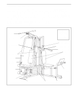
your benefit, read this manual carefully before using the weight system. If you have additional questions, please call our Customer Service Before reading further, please review the drawing below and familiarize yourself with the parts that are labeled. Lat Bar High Pulley Station Warning Decal No - Weider Pro 9400 | English Manual - Page 5
pre-attached. • Tighten all parts as you assemble them, unless instructed to do otherwise. • Assembly requires two persons. For your convenience and safety, assemble the weight system with the help of another person. • As you assemble the weight system, be sure that all parts are oriented as shown - Weider Pro 9400 | English Manual - Page 6
2. Slide the Rear Upright (74) and the Leg Press Upright (56) onto the indicated 5/16" x 2 1/2" Carriage Bolts (1) in the Stabilizer (5). The high side of the brackets on the Rear Upright and Leg Press Upright should be on the side shown. Hand tighten four 5/16" Nylon Locknuts (3) onto the Carriage - Weider Pro 9400 | English Manual - Page 7
Locknuts (3) used in steps 1-5. 5 56 8 3 1 79 11 3 3 1 82 5 6. Set two Weight Bumpers (19) on the bracket on the Base (4) as shown. Set two Weight Bumpers on the bracket on the Stabilizer (5). Stack eight Weights (25) onto each set of Weight Bumpers (19). Be sure that the pin grooves are on the - Weider Pro 9400 | English Manual - Page 8
. Lubricate the inside of the holes in the other Top Weight (65). Set the Top Weight onto the rear stack of Weights (25). Insert both Short Weight Guides (73) into the stack of Weights. Be sure that the holes in the Weight Guides are at the top, as shown. Lubricate 65 Pin 63 64 Pin Grooves 25 - Weider Pro 9400 | English Manual - Page 9
the upper ends of the Long Weight Guides (62) to the Top Frame (55) with a 5/16" x 6" Bolt (60), two 1/2" x 3/4" Spacers (61), and a 5/16" Nylon Locknut (3). 9 61 60 73 3 61 60 3 55 62 ARM ASSEMBLY 10. Locate and open the parts bag labeled "ARM ASSEMBLY." Be sure there is a Bushing (98 - Weider Pro 9400 | English Manual - Page 10
5/16" x 2 1/2" Bolts (22) and two 5/16" Nylon Locknuts (3). 22 Assemble the other Press Arm (46) in the same manner. 46 3 17 13. Identify the Nylon Locknut yet. 13 86 31 50 Welded Brackets 31 50 47 21 Attach a "V"-Pulley (50) and a Long Cable Trap (31) to the Left Arm (47) in the - Weider Pro 9400 | English Manual - Page 11
21). 74 32 49 32 84 80 67 56 33 80 CABLE ASSEMBLY 16 16. Locate and open the parts bags labeled "CABLE ASSEMBLY" and "PULLEYS." During steps 16 through 36, refer to the CABLE DIAGRAMS on pages 25-26 of this manual to verify proper cable routing. Before beginning this section, fully unwind the - Weider Pro 9400 | English Manual - Page 12
turned to hold the Cable in place. Tighten the 3/8" x 2 1/2" Bolt (86) and the 3/8" Nylon Locknut (not shown). 31 86 50 58 48 21. Attach the Pulley Bracket (20) to the Top Frame (55) with the 5/16" x 5" Bolt (68) and a 5/16" Nylon 21 68 Locknut (3). Do not over tighten the Nylon Locknut - Weider Pro 9400 | English Manual - Page 13
"U"-Bracket. Note: This may come pre-assembled. Route the High Cable (58) through the Long "U"Bracket (57) and the 3 1/2" Pulley (15) shown in the inset drawing. the inset drawing. Attach the Small "U"-Bracket (71) to the indicated Weight Tube (63) with a 5/16" x 1 3/4" Bolt (24) and a 5/16" Nylon - Weider Pro 9400 | English Manual - Page 14
a 3/8" x 3 3/4" Bolt (88), 3/8" Washer (9), and a 3/8" Nylon Locknut (21). Be sure that the parts are oriented as shown in the drawing, and that the end of the Cable with the ball is on the indicated side of the Press Frame, between the Pulley and the crossbar. 25 23 Crossbar 76 Ball 17 26. Route - Weider Pro 9400 | English Manual - Page 15
inset drawing. Attach the Small "U"-Bracket (71) to the indicated Weight Tube (63) with a 5/16" x 1 3/4" Bolt (24) and a 5/16" Nylon Locknut (3). 31. Wrap the Military Press Cable (72) around a 3 1/2" Pulley (15). Attach the Pulley to the Top Frame (55) with a 3/8" x 2" Bolt (12) and a 3/8" Nylon - Weider Pro 9400 | English Manual - Page 16
99). Make sure that the Military Press Cable (72) is between the 3 1/2" Pulley (15) and the post. Be sure that the Cable and Pulley move smoothly. The Pulley Covers (77) must be turned so that the large tabs face toward the weight system. See the inset drawing. 99 72 9 Post 15 Large tabs 77 - Weider Pro 9400 | English Manual - Page 17
onto the end of the Cable only a couple of turns, as shown in the inset drawing. Wrap the Leg Press Cable (78) around a 3 1/2" Pulley (15). Attach the Pulley to the Leg Press Upright (56) with the 3/8" x 3 3/4" Bolt (88), a 3/8" Washer (9), and a 3/8" Nylon Locknut (21). Be sure that the Cable and - Weider Pro 9400 | English Manual - Page 18
37. Locate and open the parts bag labeled "SEAT ASSEMBLY." Insert a 1/4" x 2 1/2" Carriage Bolt (92) through the center hole in a Seat Plate (37). Attach the Seat Plate to the Leg Press Backrest (85) with two 1/4" x 3/4" Screws ( - Weider Pro 9400 | English Manual - Page 19
41. Press a 1 1/2" Square Inner Cap (32) into the Leg 41 Lever (29). Lubricate the 5/16" x 2 1/4" Bolt (33). Attach the Leg Lever (29) to the Front Seat Frame (36) with the Bolt and a 5/16" Nylon Locknut (3). Insert the 3/8" x 2" Eyebolt (35) into the Leg Lever (29) from the direction shown. - Weider Pro 9400 | English Manual - Page 20
PRO 9400 Decal 42 42 45. Make sure that all parts have been properly tightened. The use of the remaining parts will be explained in ADJUSTMENTS, beginning on page 21 of this manual. Before using the weight system, pull each cable a few times to be sure that the cables move smoothly over the pulleys - Weider Pro 9400 | English Manual - Page 21
ADJUSTMENTS The instructions below describe how each part of the weight system can be adjusted. Refer to the exercise guide accompanying this manual to see how the weight system should be set up for each exercise. IMPORTANT: When attaching the lat bar or nylon strap, make sure that the attachments - Weider Pro 9400 | English Manual - Page 22
2 3/4" Carriage Bolt (14), 5/16" Washer (8) and the Seat Knob (40). For some exercises, the Seat (13) must be removed. First, be sure that the chain is not attached off the Front Upright (42). ATTACHING THE LEG LEVER TO THE LOW PULLEY STATION To use the Leg Lever (29), the seat must be attached - Weider Pro 9400 | English Manual - Page 23
listed is the resistance for each butterfly arm. The actual resistance at each weight station may vary due to differences in individual weight plates, as well as friction between the cables, pulleys, and weight guides. WEIGHT PLATES PRESS BUTTERFLY ARM ARM (lbs.) (lbs.) LEG LEVER (lbs.) HIGH - Weider Pro 9400 | English Manual - Page 24
TROUBLE-SHOOTING AND MAINTENANCE TIGHTENING THE CABLES Woven cable, the type of cable used on the weight system, can stretch slightly when it is first used. If there is slack in the cables before resistance is felt, the cables should be tightened. If any slack is felt when using the front weight - Weider Pro 9400 | English Manual - Page 25
and the cable traps have been assembled correctly. If the cables have not been correctly routed, the weight system will not function properly and damage the pulleys. Be sure that the cable traps do not touch or bind the cables. High Cable (58) and Low Cable (23) 7 5 23 4 1-High Pulley TOP VIEW - Weider Pro 9400 | English Manual - Page 26
Military Press Cable (72) and Leg Press Cable (78) 2 Military Press Cable (72) Rear Weight Stack-1 4 5 Ball End 6 8 7 1-Long "U"-Bracket 3 2 4-Rear Seat Frame 3 Leg Press Cable (78) 26 - Weider Pro 9400 | English Manual - Page 27
NOTES 27 - Weider Pro 9400 | English Manual - Page 28
Selftapping Screw (87) 5/16" Nylon Jamnut (93) 1/4" x 3/4" Screw (18) 1/4" Nylon Locknut (2) Cable Clip (53) 1 1/8" x 2 1/2" Plastic Bushing (89) 1" x 7/8" Plastic Bushing (90) 3/8" x 8" Bolt (59) "V"-Pulley (50) (Not shown to scale) 3 1/2" Pulley (15) (Not shown to scale) 1" Retainer (69) - Weider Pro 9400 | English Manual - Page 29
5/16" x 2 1/2" Carriage Bolt (1) 1/4" x 2 1/2" Carriage Bolt (91) 1/4" x 2 1/2" Carriage Bolt (92) 5/16" x 2 1/2" Bolt (22) 1/4" x 2 1/2" Screw (43) 5/16" x 2 1/4" Bolt (33) 3/8" x 2" Bolt (12) 3/8" x 2 1/2" Bolt (86) 5/16" x 2 3/4" Bolt (11) 5/16" x 2 3/4" Carriage Bolt (14) 3/8" x 3" Bolt (100) - Weider Pro 9400 | English Manual - Page 30
1" Round Cover Cap (70) 3/8" x 2" Eyebolt (35) Round Inner Cap (75) 1" Round Inner Cap (49) 1" Square Inner Cap (6) 3/4" Round Inner Cap (34) 1/2" x 3/4" Spacer (61) 5/8" x 9/16" Spacer (7) 1 1/2" Square Inner Cap (32) 2" Square Inner Cap (27) 1 3/4" Square Inner Cap (44) 2" Square Outer - Weider Pro 9400 | English Manual - Page 31
Cable 73 2 Short Weight Guide 74 1 Rear Upright 75 2 Round Inner Cap 76 1 3 1/2" Low Pulley 77 2 Pulley Cover 78 1 Leg Pad 103 1 Ab Strap # 1 User's Manual # 1 Exercise Guide Note: "#" indicates a non-illustrated part. Specifications are subject to change without notice - Weider Pro 9400 | English Manual - Page 32
15 21 66 61 3 2 12 10 57 78 11 27 74 3 3 60 3 11 10 2 65 26 25 99 9 73 87 72 91 71 27 10 43 24 21 88 10 2 8 15 63 3 3 64 12 66 15 51 19 11 8 5 11 8 21 1 83 1 51 54 53 83 52 39 103 27 56 37 92 18 77 9 15 88 11 81 66 11 15 12 11 9 83 82 21 1 101 15 66 21 80 67 - Weider Pro 9400 | English Manual - Page 33
WEIDER® PRO 9400 weight system) 3. The SERIAL NUMBER of the product (see the front cover of this manual) 4. The KEY NUMBER and DESCRIPTION of the part(s) (see the PART product through one of its authorized service centers. All repairs for which of enjoyment or use, costs of removal or installation or
-
 1
1 -
 2
2 -
 3
3 -
 4
4 -
 5
5 -
 6
6 -
 7
7 -
8
-
9
-
10
-
11
-
12
-
13
-
14
-
15
-
16
-
17
-
18
-
19
-
20
-
21
-
22
-
23
-
24
-
25
-
26
-
27
-
28
-
29
-
30
-
31
-
32
-
33
 |
 |

USER'S MANUAL
QUESTIONS?
As a manufacturer, we are com-
mitted to providing complete
customer satisfaction. If you have
questions, or if there are missing
parts, we will guarantee complete
satisfaction through assistance
from our factory.
TO AVOID UNNECESSARY
DELAYS, PLEASE CALL DIRECT
TO OUR TOLL-FREE CUSTOMER
HOT LINE. The trained techni-
cians on our customer hot line
will provide immediate assis-
tance, free of charge to you.
CUSTOMER HOT LINE:
1-800-999-3756
Mon.–Fri., 6 a.m.–6 p.m. MST
Model No. WESY39311
Serial No.
Write the serial number in the
space above for reference.
Serial Number Decal (Under Seat)
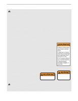
CAUTION
Read all precautions and instruc-
tions in this manual before using
this equipment. Save this manual
for future reference.
Visit our website at
www.weiderfitness.com
new products, prizes,
fitness tips, and much more!