Weider Pro 9510 English Manual
Weider Pro 9510 Manual
 |
View all Weider Pro 9510 manuals
Add to My Manuals
Save this manual to your list of manuals |
Weider Pro 9510 manual content summary:
- Weider Pro 9510 | English Manual - Page 1
Model No. WESY95100 Serial No. (Write the serial number in the space above for reference.) Serial Number Decal (under seat) QUESTIONS? As a manufacturer, we are committed to providing complete customer satisfaction. If you have questions, or find that there are missing or damaged parts, we will - Weider Pro 9510 | English Manual - Page 2
5 ADJUSTMENT 18 TROUBLE-SHOOTING AND MAINTENANCE 21 CABLE DIAGRAM 22 ORDERING REPLACEMENT PARTS Back Cover Note: A PART IDENTIFICATION CHART and a PART LIST/EXPLODED DRAWING are attached to the center of this manual. Remove the PART IDENTIFICATION CHART and the PART LIST/EXPLODED DRAWING - Weider Pro 9510 | English Manual - Page 3
precautions before using the home gym system. 1. Read all instructions in this manual and in the accompanying literature before using the home gym system. 2. It is the responsibility of the owner to ensure that all users of the home gym system are adequately informed of all precautions. 3. If - Weider Pro 9510 | English Manual - Page 4
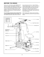
WEIDER® 9510 will help you to achieve the specific results you want. Service model number is WESY95100. The serial number can be found on a decal attached to the WEIDER® 9510 (see the front cover of this manual). For your benefit, read this manual carefully before using the WEIDER® 9510 Home Gym - Weider Pro 9510 | English Manual - Page 5
information and instructions: • Place all parts of the WEIDER 9510 parts bag. • For help identifying the small parts used in assembly, use the PART IDENTIFICATION CHART located in the center of this manual. Note: Some small parts may have been preattached for shipping. If a part is not in the parts - Weider Pro 9510 | English Manual - Page 6
shown. Stack eight Weights (25) onto the Weight Bumpers (19). Be sure that the pin grooves are all on the indicated side and that the "WEIDER" logos are on top. 3 27 3 4 11 8 55 56 44 11 8 49 44 Crossbar 42 - Weider Pro 9510 | English Manual - Page 7
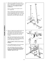
6" Bolt (60), two 1/2" x 3/4" Spacers (61), and a 5/16" Nylon Locknut (3). Be sure that the Pulley Bracket (20) is in front of the right Weight Guide (62) as shown. 7. Press a 1" x 7/8" Plastic Bushing (75) onto each welded spacer on the Press Frame (17). Slide the Press Frame into place on the - Weider Pro 9510 | English Manual - Page 8
ARM ASSEMBLY 8. Wet the handle of one Press Arm (46) with 8 soapy water. Slide a Hand Grip (31) onto the handle. Press a 1" Round Inner Cap (49) into the other end of the handle. Press a 1 3/4" Square Inner Cap (44) into the Press Arm. 44 Attach the Press Arm (46) to one side of the 49 - Weider Pro 9510 | English Manual - Page 9
CABLE ASSEMBLY 11. During steps 11 through 27, refer to the CABLE DIAGRAM on page 22 of this manual to verify proper cable routing. Before beginning this section, identify the Long Cable (23), the Medium Cable (58), and the Short Cable (35) by comparing - Weider Pro 9510 | English Manual - Page 10
Pulley move smoothly. 15 66 12 21 57 18. Note: The Pulley in this drawing is pre- 18 assembled. It is shown disassembled for easy part identification. 23 15 Bracket 12 Route the Long Cable (23) around the 3 1/2" Pulley (15) attached to the bracket on the Top Frame (55). Tighten the - Weider Pro 9510 | English Manual - Page 11
Front Upright (42) from the direction shown. Hand tighten the 3/8" Nylon Locknut (21) with the 3/8" Flat Washer (9) onto the Bolt. Be sure that all parts are oriented as shown. Do not tighten the Nylon Locknut yet. 21. The indicated 3/8" x 3 3/4" Bolt (71) has also been inserted from the wrong side - Weider Pro 9510 | English Manual - Page 12
CABLE ASSEMBLY 22. Locate the Medium Cable (58). Route the 22 Medium Cable (58) under the 3 1/2" Pulley (15) attached to the lower hole in the Press Frame (17). Be sure that the end of the Cable with the ball is on the indicated side of the Press Frame and that the Cable is between the - Weider Pro 9510 | English Manual - Page 13
CABLE ASSEMBLY 26. Attach the end of the Medium Cable (58) to 26 the Long "U"-Bracket (57) with a 1/4" Nylon Locknut (2) and a 1/4" Flat Washer (10). Do not completely tighten the Nylon Locknut. It should be threaded onto the end of the Cable so only a couple of threads are showing above the - Weider Pro 9510 | English Manual - Page 14
SEAT ASSEMBLY 29. Press a 1 1/2" Square Inner Cap (32) into the 29 Seat Frame (36). Insert the 1/4" x 2" Carriage Bolt (38) into the center hole in the Seat Plate (37). Attach the Seat Plate to the Seat (13) with two 1/4" x 1/2" Screws (18). Insert the 1/4" x 2" Carriage Bolt (38) into the - Weider Pro 9510 | English Manual - Page 15
Bolt (90) into the keyhole in the Leg Lever (29). Be sure that the shoulder of the Carriage Bolt is firmly seated in the square part of the keyhole. See the right inset drawing. Orient the Short Cable (35) and the Curl Bar (86) as shown. Tighten the indicated 5/16" Nylon - Weider Pro 9510 | English Manual - Page 16
36. Press 1 1/2" Square Inner Caps (32) into the ends of the Left VKR Arm (79) and the Right VKR Arm (80). Press 1" Round Inner Caps (49) into the ends of the handles on the Left VKR Arm and the Right VKR Arm. Attach the Left VKR Arm (79) and the Right VKR Arm (80) to the Rear Upright (56) with two - Weider Pro 9510 | English Manual - Page 17
(OTHER SIDE) BUTTERFLY PRO 9510 VKR BENCH PRESS PREACHER CURL LEG DEVELOPER LOW PULLEY 39. Make sure that all parts have been properly tightened. The use of the remaining parts will be explained in ADJUSTMENT, beginning on page 18 of this manual. Before using the home gym system, pull each - Weider Pro 9510 | English Manual - Page 18
ADJUSTMENT The instructions below describe how each part of the home gym system can be adjusted. Refer to the exercise guide accompanying this manual to see how the home gym system should be set up for each exercise. IMPORTANT: When attaching the lat bar or nylon strap, make sure that the - Weider Pro 9510 | English Manual - Page 19
ATTACHING AND REMOVING THE SEAT Set the bracket on the Seat Frame (36) on the indicated pins on the Front Upright (42). Attach the Seat Frame to the Front Upright with the 5/16" x 2 3/4" Carriage Bolt (14) and the Seat Knob (40). For some exercises, the Seat Frame (36) must be removed. First, be - Weider Pro 9510 | English Manual - Page 20
ADJUSTING THE SHORT CABLE The position of the Curl Bar (86) can be changed by adjusting the Short Cable (35). To adjust the Short Cable (35), remove the 5/16" x 3/4" Bolt (89), 5/16" Flat Washer (8), and 5/16" Nylon Locknut (3). Re-attach the Short Cable (35) to one of the other holes in the Leg - Weider Pro 9510 | English Manual - Page 21
TROUBLE-SHOOTING AND MAINTENANCE Inspect and tighten all parts each time you use the home gym system. Replace any worn parts immediately. The home gym system can be cleaned using a damp cloth and mild non-abrasive detergent need to be replaced, see the back cover of this manual. 21 12 2 58 21 - Weider Pro 9510 | English Manual - Page 22
the diagram to be sure that the cables and the cable traps have been assembled correctly. If the cables have not been correctly routed, the home gym system will not function properly and damage may occur. The inset drawings show the proper positioning of the cable traps. The cable traps should be - Weider Pro 9510 | English Manual - Page 23
NOTES 23 - Weider Pro 9510 | English Manual - Page 24
to give the following information: 1. The MODEL NUMBER of the product (WESY95100). 2. The NAME of the product (WEIDER® 9510 Home Gym System). 3. The SERIAL NUMBER of the product (see the front cover of this manual). 4. The KEY NUMBER and DESCRIPTION of the part(s) (see the PART LIST/EXPLODED DRAWING - Weider Pro 9510 | English Manual - Page 25
REMOVE THIS PART IDENTIFICATION CHART FROM THE MANUAL This chart is provided to help you identify the small parts used in assembly. Important: Some parts may have been pre-assembled for shipping purposes. If you cannot find a part in the parts bags, check to see if it has been pre-assembled. The - Weider Pro 9510 | English Manual - Page 26
5/8" x 9/16" Spacer (73)-1 1/2" x 1/2" Bushing (87)-1 1/2" x 3/4" Spacer (61)-2 1" x 7/8" Plastic Bushing (75)-2 5/8" x 3/8" Bushing (91)-1 1" Square Inner Cap (65)-1 1 3/4" Square Inner Cap (44)-6 1 1/2" Square Inner Cap (32)-5 2" Square Inner Cap (27)-2 2" Square Outer Cap (51)-2 - Weider Pro 9510 | English Manual - Page 27
1/4" Nylon Locknut (2)-3 5/16" Nylon Locknut(3)-23 3/8" Nylon Locknut (21)-12 1/4" Flat Washer (10)-12 1/4" x 2" Screw (24)-5 1/4" x 2" Carriage Bolt (38)-1 3/8" x 2" Bolt (12)-3 5/16" x 2 1/4" Bolt (33)-1 5/16" Flat Washer (8)-8 1/4" x 2 1/2" Screw (43)-4 3/8" Flat Washer (9)-4 5/16" x 2 1/2" - Weider Pro 9510 | English Manual - Page 28
REMOVE THIS PART LIST/EXPLODED DRAWING FROM THE MANUAL 81 - Weider Pro 9510 | English Manual - Page 29
PART LIST-Model No. WESY95100 Key No. Qty. Description Key No. Qty. 1 3 2 3 3 23 4 " x 6" Bolt 1/2" x 3/4" Spacer Weight Guide Weight Tube Weight Tube Bumper 1" Square Inner Cap 3/8" Bushing User's Manual Exercise Poster Note: "#" indicates a non-illustrated part. Specifications are subject - Weider Pro 9510 | English Manual - Page 30
EXPLODED DRAWING-Model No. 831.159460 66 15 21 2 10 57 12 58 27 55 68 20 21 3 12 15 66 31 78 81 80 32 10 24 35 86 31 49 46 91 90 49 46 49 22 21 17 16 71 9 3 15 21 66 73 58 59 75 R12 EXPLODED DRAWING-Model No. WESY95100
-
 1
1 -
 2
2 -
 3
3 -
 4
4 -
 5
5 -
 6
6 -
 7
7 -
8
-
9
-
10
-
11
-
12
-
13
-
14
-
15
-
16
-
17
-
18
-
19
-
20
-
21
-
22
-
23
-
24
-
25
-
26
-
27
-
28
-
29
-
30
 |
 |

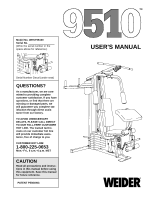
USER'S MANUAL
QUESTIONS?
As a manufacturer, we are com-
mitted to providing complete
customer satisfaction. If you have
questions, or find that there are
missing or damaged parts, we
will guarantee you complete sat-
isfaction through direct assis-
tance from our factory.
TO AVOID UNNECESSARY
DELAYS, PLEASE CALL DIRECT
TO OUR TOLL-FREE CUSTOMER
HOT LINE. The trained techni-
cians on our customer hot line
will provide immediate assis-
tance, free of charge to you.
CUSTOMER HOT LINE:
1-800-225-0653
Mon.–Fri., 6 a.m.–6 p.m. MST
Model No. WESY95100
Serial No.
(Write the serial number in the
space above for reference.)
PATENT PENDING
CAUTION
Read all precautions and instruc-
tions in this manual before using
this equipment. Save this manual
for future reference.
Serial Number Decal (under seat)
TM