Weider Pro 9930 User Manual - Page 10
Cable Assembly
 |
View all Weider Pro 9930 manuals
Add to My Manuals
Save this manual to your list of manuals |
Page 10 highlights
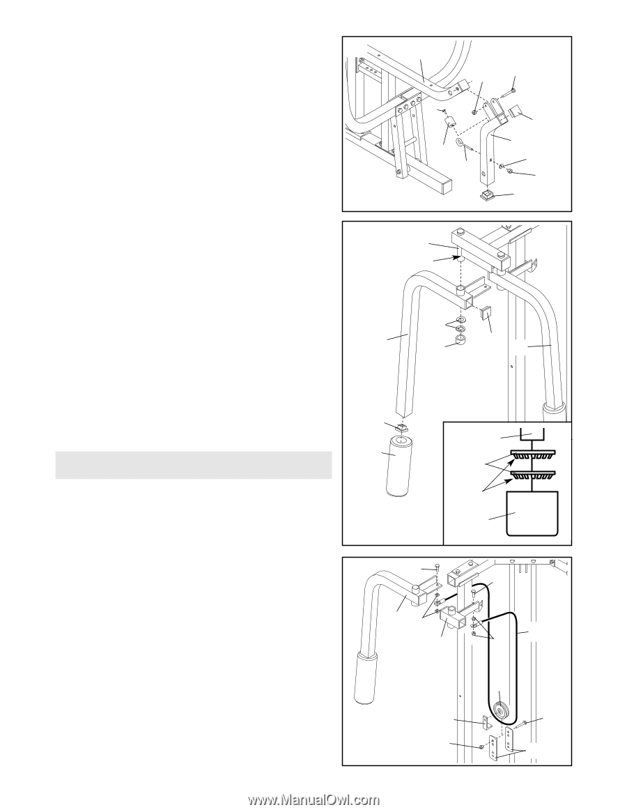
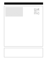
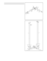
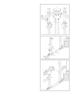
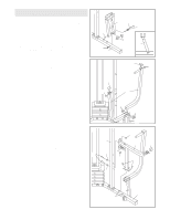
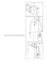
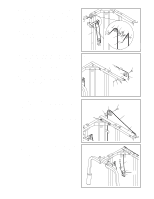
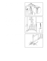
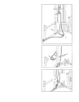
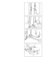
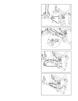
12. Press two 1 1/2" Square Inner Caps (79) into the Leg Lever (49). Insert a Bumper (33) between the brackets 12 on the Leg Lever. Attach the Bumper to the Leg Lever with a #10 x 1" Screw (32). Slide the bracket on the Leg Lever (49) onto the Press Seat Frame (52). Attach the Leg Lever to the Press Seat Frame with a 5/16" x 2 1/4" Bolt (81) and a 5/16" Jam Nut (90). Do not overtighten the Jam Nut. The Leg Lever must pivot easily. Attach a 3/8" x 2 1/2" Eyebolt (83) to the Leg Lever (49) with a 3/8" Flat Washer (17) and 3/8" Nylon Locknut (4). 52 90 81 32 33 83 79 49 17 4 79 13. Press a 1 3/4" Square Inner Cap (37) into each end of 13 the Right Butterfly Arm (68). Wet the lower end of the Arm with soapy water. Slide a 10" Pad (65) onto the lower end of the Arm. 64 Lubricate Lubricate the indicated axle on the Butterfly Top Frame (64). Have a second person slide the Right Butterfly Arm (68) onto the axle, as shown. Refer to the inset draw- ing. Place two 1" Retainers (25), with the teeth down- 25 ward, on top of an inverted 1" Round Cap (26). Using 68 a hammer, tap the 1" Round Cap and the Retainers 26 onto the axle to secure the Right Butterfly Arm. Repeat this step to assemble the Left Butterfly Arm (67). 37 67 Cable Assembly 37 64 65 25 14. Open the parts bag labelled "CABLE ASSEMBLY AND PULLEYS." For cable identification and routing during steps 14-32, refer to the CABLE DIAGRAMS and CABLE ID CHART on pages 19 and 20. Teeth 26 Insert two 3/8" x 1" Bolts (15) into the welded brackets 14 on the Left and Right Butterfly Arms (67, 68). Secure 15 15 each Bolt with a 3/8" Jam Nut (18). Identify the Short Cable (71). It has a closed loop on each end. Slide one end of the Cable onto each of the 3/8" x 1" Bolts (15). Secure the Cable to the Bolts with 3/8" Jam Nuts (18). Do not overtighten the Jam Nuts. 68 18 67 18 Remove both 3 1/2" Pulleys (5) from the pre-assembled Adjustable Pulley Plates (44). Wrap the Short Cable (71) around a Pulley in the direction shown. Attach the Pulley and a Cable Trap (39) to the top hole in the two Adjustable Pulley Plates with a 3/8" x 2" Bolt (35) and a 3/8" Nylon Locknut (4). Make sure that the Cable Trap and the Pulley Plates are oriented as shown. 5 39 4 71 35 44 10
-
 1
1 -
2
-
3
-
4
-
 5
5 -
 6
6 -
 7
7 -
 8
8 -
 9
9 -
 10
10 -
 11
11 -
 12
12 -
 13
13 -
 14
14 -
 15
15 -
16
-
17
-
18
-
19
-
20
-
21
-
22
-
23
-
24
-
25
-
26
-
27
-
28
-
29
-
30
-
31
 |
 |