Weslo Cadence M5 Treadmill Uk Manual - Page 7
Damaged When The Power Is Turned
 |
View all Weslo Cadence M5 Treadmill manuals
Add to My Manuals
Save this manual to your list of manuals |
Page 7 highlights
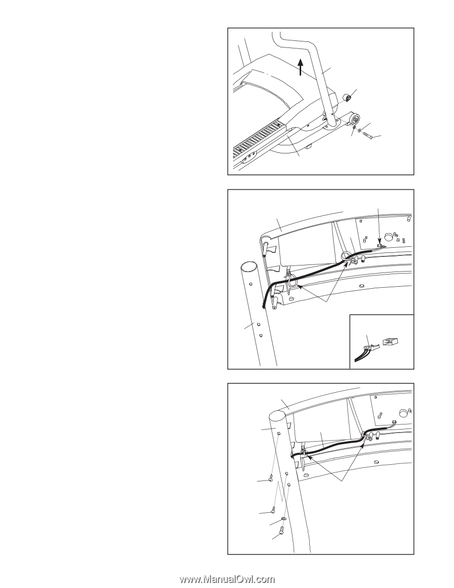
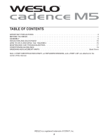
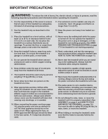
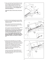
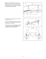
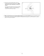
3. Have a second person lift and hold the front end of the Frame (51). Hold a Frame Spacer (11) be- 3 tween the Right Handrail (54) and the Frame. Attach the Right Handrail to the Frame with a Frame Pivot Bolt (1), a Frame Washer (14), and a Handrail Star Washer (9). Do not tighten the Frame Pivot Bolts yet. Repeat this step on the left side of the treadmill. 54 11 14 1 9 51 4. Hold the Console Assembly (91) near the Right Handrail (54). Touch the Right Handrail to dis- 4 charge any static. 91 Next, remove the wire from the end of the Wire Harness (98). Insert the end of the Wire Harness through the two looped plastic ties. Then, press the end of the Wire Harness (98) into the connector on the back of the Console Assembly (91) in the location shown. The end of the Wire Harness should slide easily into the connector and snap into place. If it does not, turn the end of the Wire Harness and then try again. IF THE CONNECTORS ARE NOT CON- NECTED PROPERLY, THE CONSOLE MAY BE DAMAGED WHEN THE POWER IS TURNED 54 ON. Connector 98 Plastic Ties 98 5. Set the Console Assembly (91) on the Right Handrail (54) and the Left Handrail (not shown). Partially tighten two Crossbar Screws (5) with two Crossbar Star Washers (12) (only one of each is shown) into the Handrails and the Console Assembly. Then, partially tighten four Console Screws (7) (only two are shown) into the Handrails and the Console Assembly. Then, tighten all six Screws. Insert the excess Wire Harness (98) down into the Right Handrail (54). Tighten the two plastic ties around the Wire Harness, and then cut off the ends of the plastic ties. 5 91 54 7 7 12 5 7 98 Plastic Ties
-
 1
1 -
 2
2 -
 3
3 -
 4
4 -
 5
5 -
 6
6 -
 7
7 -
 8
8 -
 9
9 -
 10
10 -
 11
11 -
 12
12 -
13
-
14
-
15
-
16
-
17
-
18
-
19
-
20
-
21
-
22
-
23
 |
 |