Whirlpool GH7208XRQ Installation Instructions
Whirlpool GH7208XRQ - Microwave Manual
 |
UPC - 050946996202
View all Whirlpool GH7208XRQ manuals
Add to My Manuals
Save this manual to your list of manuals |
Whirlpool GH7208XRQ manual content summary:
- Whirlpool GH7208XRQ | Installation Instructions - Page 1
Holes in Rear Wall 7 Attach Mounting Plate to Wall 7 Prepare Upper Cabinet 8 Install the Microwave Oven 9 Install Filters 10 Complete Installation 10 VENTING DESIGN SPECIFICATIONS 11 ASSISTANCE 12 Replacement Parts 12 Accessories 12 MICROWAVE HOOD COMBINATION SAFETY Your safety and the - Whirlpool GH7208XRQ | Installation Instructions - Page 2
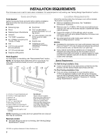
: Upper cabinet template Mounting plate (attached to back of microwave oven) Aluminum grease filters Charcoal filters (Depending on model, charcoal filters may not be included. See Use and Care Guide.) NOTE: Depending on model, aluminum grease filter and charcoal filter may be combined. Materials - Whirlpool GH7208XRQ | Installation Instructions - Page 3
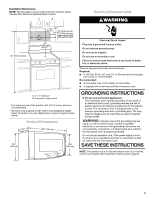
of range/cooktop below. Product codes and ordinances. Required: ■ A 120 Volt, 60 Hz, AC only, 15- or 20-amp electrical supply with a fuse or circuit breaker. Recommended: ■ A time-delay fuse or time-delay circuit breaker. ■ A separate circuit serving only this microwave oven. GROUNDING INSTRUCTIONS - Whirlpool GH7208XRQ | Installation Instructions - Page 4
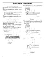
INSTRUCTIONS Remove Mounting Plate Depending on your model, the mounting plate may be in the foam packaging, or it may be attached to the back of the microwave oven. NOTE: To avoid possible damage to the work surface, cover the work surface. 1. Remove any remaining contents from the microwave oven - Whirlpool GH7208XRQ | Installation Instructions - Page 5
on the right side of the damper vent opening, as shown. Then secure with mounting screw. A B C D A. Diagonal wire cutting pliers B. Top of microwave oven C. Roof damper vent cover D. Perforations 3. Save the cover for possible change of venting method in the future. NOTE: Do not install damper - Whirlpool GH7208XRQ | Installation Instructions - Page 6
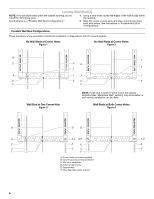
studs exist within the cabinet opening, do not install the microwave oven. 1. Using a stud finder, locate the edges of the Studs at Corner Holes Figure 1 No Wall Studs at Corner Holes Figure 2 MOUNTING PLATE MOUNTING PLATE MOUNTING PLATE MOUNTING PLATE B C C C B D D A A A A E E E - Whirlpool GH7208XRQ | Installation Instructions - Page 7
microwave oven must be installed on a minimum of 1 wall stud, preferably 2, using a minimum of 1 lag screw, preferably 2. 1. Using measuring tape, find and clearly mark the vertical centerline of the opening. A A. Centerline 2. With the support 1 wall stud, the mounting plate must attach to the wall - Whirlpool GH7208XRQ | Installation Instructions - Page 8
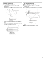
(Figure 3) 1. With the support tabs of the mounting plate facing forward, insert a 1/4- use as guides. ■ If the wall behind the microwave oven (as installed) has a partial wall covering (for example, tile backsplash), be sure the "Rear Wall" arrows align to the thickest part - Whirlpool GH7208XRQ | Installation Instructions - Page 9
2 or more people, lift microwave oven and hang it on support tabs at the bottom of mounting plate. NOTE: To avoid damage to the microwave oven, do not grip or use the door or door handle while the microwave oven is being handled. 4. With front of microwave oven still tilted, thread power supply - Whirlpool GH7208XRQ | Installation Instructions - Page 10
a circuit breaker has not tripped. Replace the fuse or reset the circuit breaker. If the problem continues, call an electrician. ■ Check that the power supply cord is plugged into a grounded 3 prong outlet. ■ See the User Instructions for troubleshooting information. Installation is now complete - Whirlpool GH7208XRQ | Installation Instructions - Page 11
, and rectangular to round transition is used, be sure there is at least 3" (7.6 cm) of clearance between the top of the microwave oven and the transition piece. See "Rectangular to Round Transition" illustration. Rectangular to Round Transition NOTE: The minimum 3" (7.6 cm) clearance must exist - Whirlpool GH7208XRQ | Installation Instructions - Page 12
toll free number listed in the User Instructions. Following is a list of available replacement parts. You will need your model number located on the front facing of the microwave oven opening, behind the door. ■ Damper Assembly ■ Mounting Plate ■ Upper Cabinet Template ■ Mounting Screw Kit (includes
-
 1
1 -
 2
2 -
 3
3 -
 4
4 -
 5
5 -
 6
6 -
 7
7 -
8
-
9
-
10
-
11
-
12
 |
 |
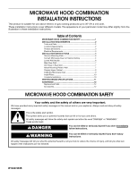
MICROWAVE HOOD COMBINATION
INSTALLATION INSTRUCTIONS
MICROWAVE HOOD COMBINATION SAFETY
This product is suitable for use above electric or gas cooking products up to 36" (91.4 cm) wide.
These installation instructions cover different models. The appearance of your particular model may differ slightly from the
illustration in these installation instructions.
Table of Contents
MICROWAVE HOOD COMBINATION SAFETY
..............................
1
INSTALLATION REQUIREMENTS
...................................................
2
Tools and Parts
...............................................................................
2
Location Requirements
...................................................................
2
Product Dimensions
.......................................................................
3
Electrical Requirements
..................................................................
3
INSTALLATION INSTRUCTIONS
.....................................................
4
Remove Mounting Plate
.................................................................
4
Convert Microwave Oven to External Venting
...............................
4
Locate Wall Stud(s)
.........................................................................
6
Mark Rear Wall
................................................................................
7
Drill Holes in Rear Wall
....................................................................
7
Attach Mounting Plate to Wall
........................................................
7
Prepare Upper Cabinet
...................................................................
8
Install the Microwave Oven
............................................................
9
Install Filters
..................................................................................
10
Complete Installation
....................................................................
10
VENTING DESIGN SPECIFICATIONS
............................................
11
ASSISTANCE
...................................................................................
12
Replacement Parts
.......................................................................
12
Accessories
...................................................................................
12
W10247293B
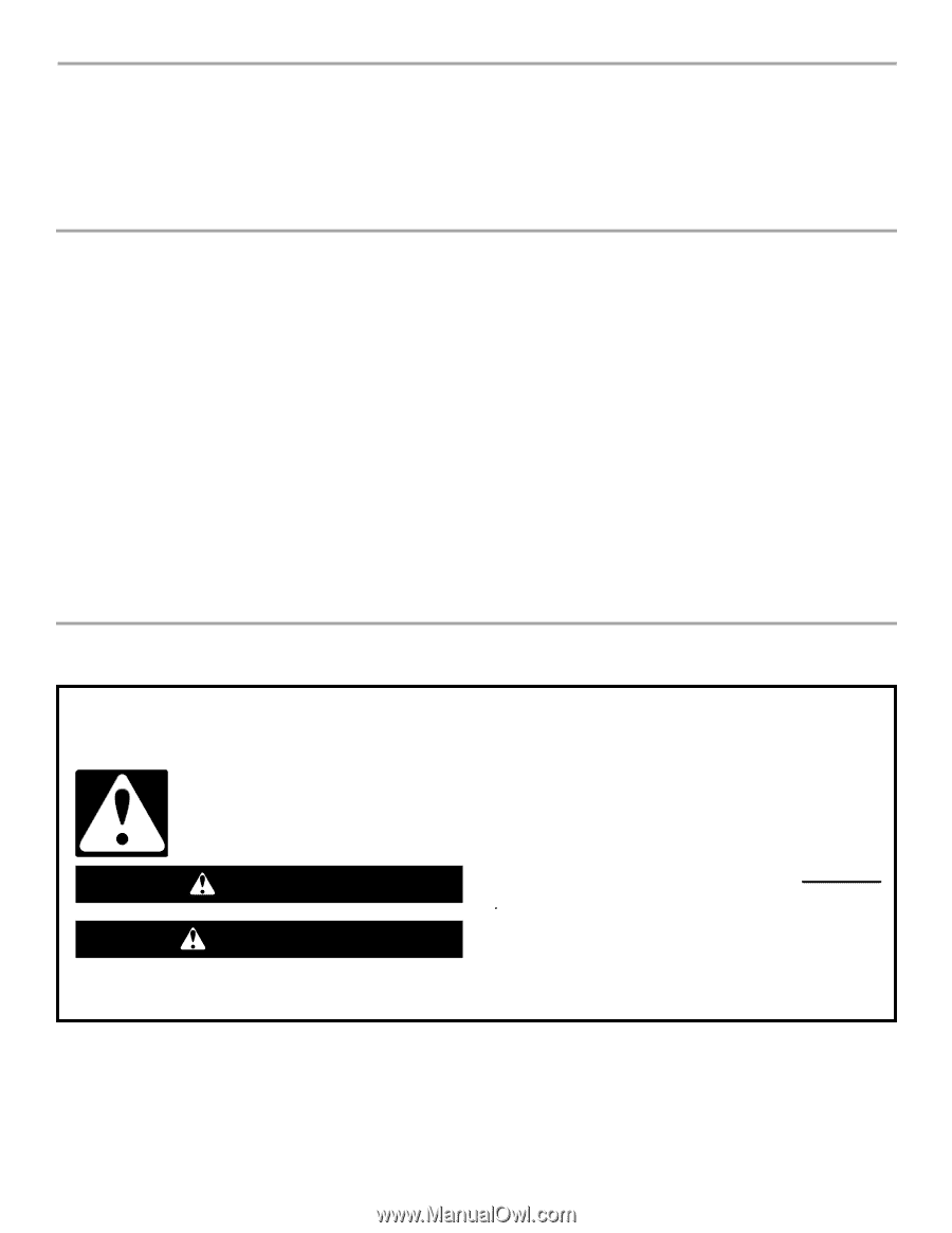
You can be killed or seriously injured if you don't immediately
You
can be killed or seriously injured if you don't follow
All safety messages will tell you what the potential hazard is, tell you how to reduce the chance of injury, and tell you what can
happen if the instructions are not followed.
Your safety and the safety of others are very important.
We have provided many important safety messages in this manual and on your appliance. Always read and obey all safety
messages.
This is the safety alert symbol.
This symbol alerts you to potential hazards that can kill or hurt you and others.
All safety messages will follow the safety alert symbol and either the word “DANGER” or “WARNING.”
These words mean:
follow instructions.
instructions.
DANGER
WARNING