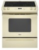
Whirlpool GY397LXUT Installation Instructions
Whirlpool GY397LXUT - 30" SELF CLEAN Manual
 |
UPC - 883049127675
View all Whirlpool GY397LXUT manuals
Add to My Manuals
Save this manual to your list of manuals |
Whirlpool GY397LXUT manual content summary:
- Whirlpool GY397LXUT | Installation Instructions - Page 1
des matières RANGE SAFETY 2 INSTALLATION REQUIREMENTS 3 Tools and Parts 3 Location Requirements 3 Electrical Requirements - U.S.A. Only 4 Electrical Requirements - Canada Only 5 Countertop Preparation 5 INSTALLATION INSTRUCTIONS 6 Unpack Range 6 Adjust Leveling Legs 6 Install Anti-Tip - Whirlpool GY397LXUT | Installation Instructions - Page 2
important. We have provided many important safety messages in this manual and on your appliance. Always read and obey all safety messages. This is the reduce the chance of injury, and tell you what can happen if the instructions are not followed. WARNING Tip Over Hazard A child or adult can tip - Whirlpool GY397LXUT | Installation Instructions - Page 3
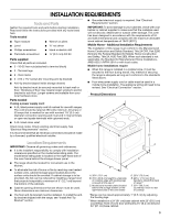
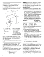
REQUIREMENTS Tools and Parts Gather the required tools and parts before starting installation. Read and follow the instructions provided with any cord or cable must be used in a mobile home installation. The appliance wiring will need to be revised. See "Electrical Connection" section. Product - Whirlpool GY397LXUT | Installation Instructions - Page 4
electric shock. Check with a qualified electrician or service technician if you are in doubt as to whether the appliance is properly grounded. Do not modify the power type of electrical connection you will be using and follow the instructions provided for it here. ■ Range must be connected to the - Whirlpool GY397LXUT | Installation Instructions - Page 5
on the supply end. Connectors on the appliance end must be provided at the point the power supply cord enters the appliance. This uses a 3-wire receptacle of adequate and in conformance with CSA Standard C22.1, Canadian Electrical Code, Part 1 - latest edition, and all local codes and ordinances. A - Whirlpool GY397LXUT | Installation Instructions - Page 6
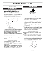
parts package from inside oven. 3. Pull storage drawer out completely. 4. Remove and discard cardboard cross support. B A A. Storage drawer B. Cardboard cross support tip bracket, if the range is moved. Failure to follow these instructions can result in death or serious burns to children and adults. - Whirlpool GY397LXUT | Installation Instructions - Page 7
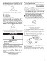
new 40 amp power supply cord. Plug into a grounded outlet. Failure to follow these instructions can result in death, fire, or electrical shock. Electrical Shock Hazard Disconnect power before servicing. Use 8 gauge copper or 6 gauge aluminum wire. Electrically ground range. Failure to follow these - Whirlpool GY397LXUT | Installation Instructions - Page 8
4. Add strain relief. Style 1: Power supply cord strain relief ■ Assemble a UL listed strain relief in the opening. A ■ Lift range back panel up and off. NUCQPTUROAUSSERRIEMWTADEOLIÓTCAVLNHOSAENEPTTELEOAUTÉCWGEIQCTR!EATUUCRRRESAICTCEESAOLORD A. UL listed strain relief ■ Feed the power supply cord - Whirlpool GY397LXUT | Installation Instructions - Page 9
■ In an area where local codes prohibit grounding through the neutral 1. Part of metal ground strap must be cut out and removed. B A. Removable panel and screws on rear of range. 6. Complete installation following instructions for your type of electrical connection: 4-wire (recommended) 3-wire - Whirlpool GY397LXUT | Installation Instructions - Page 10
5. Use ³⁄₈" nut driver to connect the neutral (white) wire to the center terminal block post with one of the 10-32 hex nuts. 2. Use ³⁄₈" nut driver to connect the neutral (white) wire to the center terminal block post with one of the 10-32 hex nuts. A F A E B C E D A. 10-32 hex nut B. - Whirlpool GY397LXUT | Installation Instructions - Page 11
1. Part of metal ground strap must be cut out and removed. A B C 4. Attach terminal lugs to line 1 (black), neutral (white), and line 2 (red) wires. Loosen (do not - Whirlpool GY397LXUT | Installation Instructions - Page 12
3-wire connection: Direct Wire Use this method only if local codes permit connecting ground conductor to neutral supply wire. 1. Pull the conduit through the hole and conduit plate on bottom of range. Allow enough slack to easily attach the wiring to the terminal block. A 3. Use ³⁄₈" nut driver to - Whirlpool GY397LXUT | Installation Instructions - Page 13
instruction on range operation. If range does not operate, check the following: ■ Household fuse is intact and tight; or circuit breaker has not tripped. ■ Range is plugged into an outlet. ■ Electrical supply is connected. ■ See "Troubleshooting" in the Use and Care Guide servicing. Replace all parts - Whirlpool GY397LXUT | Installation Instructions - Page 14
est le danger potentiel et vous disent comment réduire le risque de blessure et ce qui peut se produire en cas de non-respect des instructions. AVERTISSEMENT Risque de basculement Un enfant ou une personne adulte peut faire basculer la cuisinière ce qui peut causer un décès. Joindre la bride - Whirlpool GY397LXUT | Installation Instructions - Page 15
de commencer l'installation. Lire et suivre les instructions fournies avec les outils indiqués ici. Outils çu pour l'utilisation avec une cuisinière. Pour service 250 volts minimum, 40 A ou 50 A, Part 3280 (anciennement Federal Standard for Mobile Home Construction and Safety, Title 24, HUD Part - Whirlpool GY397LXUT | Installation Instructions - Page 16
d'un ensemble hotte/microondes au-dessus de la cuisinière, suivre les instructions fournies avec la hotte concernant les dimensions de dégagement à respecter au-dessus de remisage) D. 29⁷⁄₈" (75,9 cm) E. Longueur de la poignée au support à l'arrière de la cuisinière : 28 71,9 cm)** F. Du coin - Whirlpool GY397LXUT | Installation Instructions - Page 17
Relier la cuisinière à la terre. Le non-respect de cette instruction peut causer un décès, un incendie ou un choc électrique. Si le ce que la prise de courant murale soit placée à portée de la position de service finale de la cuisinière. Préparation du plan de travail (pour cuisinières encastré - Whirlpool GY397LXUT | Installation Instructions - Page 18
pour déplacer et installer la cuisinière. Le non-respect de cette instruction peut causer une blessure au dos ou d'autre blessure. 1. Ôter les mat le plancher dans le sens de la longueur derrière la cuisinière à titre de support de la cuisinière lorsque celle-ci est placée sur sa partie postérieure. - Whirlpool GY397LXUT | Installation Instructions - Page 19
un linge doux. Pour plus d'informations, lire la section "Entretien de la cuisinière" dans le Guide d'utilisation et d'entretien. 6. Lire la section "Utilisation de la cuisinière" dans le Guide d'utilisation et d'entretien. 7. Brancher le cordon électrique dans la prise de courant appropriée. Faire - Whirlpool GY397LXUT | Installation Instructions - Page 20
9. Mettre l'appareil sous tension. Mettre en marche les brûleurs de surface et le four. Pour des instructions spécifiques concernant l'utilisation de la cuisinière, consulter le Guide d'utilisation et d'entretien. Si la cuisinière ne fonctionne pas, contrôler ce qui suit : ■ Les fusibles du domicile
-
 1
1 -
 2
2 -
 3
3 -
 4
4 -
 5
5 -
 6
6 -
 7
7 -
8
-
9
-
10
-
11
-
12
-
13
-
14
-
15
-
16
-
17
-
18
-
19
-
20
 |
 |

INSTALLATION INSTRUCTIONS
SLIDE-IN ELECTRIC RANGES
INSTRUCTIONS D’INSTALLATION DES CUISINIÈRES
ÉLECTRIQUES ENCASTRABLE
Table of Contents/Table des matières
RANGE SAFETY
.............................................................................
2
INSTALLATION REQUIREMENTS
................................................
3
Tools and Parts
............................................................................
3
Location Requirements
................................................................
3
Electrical Requirements - U.S.A. Only
.........................................
4
Electrical Requirements - Canada Only
.......................................
5
Countertop Preparation
...............................................................
5
INSTALLATION INSTRUCTIONS
..................................................
6
Unpack Range
..............................................................................
6
Adjust Leveling Legs
....................................................................
6
Install Anti-Tip Bracket
.................................................................
6
Electrical Connection - U.S.A. Only
.............................................
7
Verify Anti-Tip Bracket Location
................................................
12
Level Range
................................................................................
12
Complete Installation
.................................................................
13
Moving the Range
......................................................................
13
SÉCURITÉ DE LA CUISINIÈRE
...................................................
14
EXIGENCES D'INSTALLATION
...................................................
15
Outillage et pièces
......................................................................
15
Exigences d'emplacement
.........................................................
15
Spécifications électriques
..........................................................
17
Préparation du plan de travail
....................................................
17
INSTRUCTIONS D'INSTALLATION
.............................................
18
Déballage de la cuisinière
..........................................................
18
Réglage des pieds de nivellement
.............................................
18
Installation de la bride antibasculement
....................................
18
Vérification de l'emplacement de la bride antibasculement
......
19
Réglage de l'aplomb de la cuisinière
.........................................
19
Achever l'installation
..................................................................
19
Déplacement de la cuisinière
.....................................................
20
IMPORTANT:
Save for local electrical inspector's use.
IMPORTANT :
À conserver pour consultation par l'inspecteur local des installations électriques.
8101P750-60