Whirlpool MH2175XST Installation Instructions
Whirlpool MH2175XST Manual
 |
View all Whirlpool MH2175XST manuals
Add to My Manuals
Save this manual to your list of manuals |
Whirlpool MH2175XST manual content summary:
- Whirlpool MH2175XST | Installation Instructions - Page 1
covered under the warranty. Table of Contents MICROWAVE HOOD COMBINATION SAFETY 1 INSTALLATION REQUIREMENTS 2 Tools and Parts 2 Location Requirements 2 Product Dimensions 3 Electrical Requirements 3 INSTALLATION INSTRUCTIONS 4 Remove Mounting Plate 4 Rotate Blower Motor 4 Locate Wall Stud - Whirlpool MH2175XST | Installation Instructions - Page 2
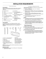
venting) Not Shown: Upper cabinet template Mounting plate (attached to back of microwave oven) Aluminum grease filters Charcoal filters (Depending on model, charcoal filters may not be included. See Use and Care Guide.) NOTE: Depending on model, aluminum grease filter and charcoal filter may be - Whirlpool MH2175XST | Installation Instructions - Page 3
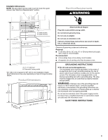
may vary depending on type of range/cooktop below. Product Dimensions 17¹⁄₄" (43.8 cm) 16¹⁄₄" (41.3 cm) (401.05³c⁄₄m") 29⁷⁄₈" (76.0 cm) GROUNDING INSTRUCTIONS ■ For all cord connected appliances: The microwave oven must be grounded. In the event of an electrical short circuit, grounding - Whirlpool MH2175XST | Installation Instructions - Page 4
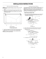
(multiple locations) 3. Tape the microwave oven door closed so that door does not swing open while the microwave oven is being handled. NOTE: Do not grip or use the door or door handle while the microwave oven is being handled. A Screws B. Damper plate 2. Keep damper plate and screws together and - Whirlpool MH2175XST | Installation Instructions - Page 5
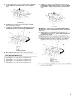
in Step 3 cannot be reattached to the microwave oven. 7. Reattach damper plate. Make sure damper plate tabs are inserted into the slots in the top of the microwave oven. A D B C A. Screws B. Damper plate C. Slots D. Damper plate tabs 8. Secure damper plate with 2 screws removed in Step 1 of "Wall - Whirlpool MH2175XST | Installation Instructions - Page 6
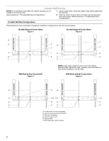
not install the microwave oven. 1. PLATE MOUNTING PLATE MOUNTING PLATE MOUNTING PLATE B D B A A,D A,D A,D E E E E C C C C F F A. Corner holes (on mounting plate) B. Cabinet opening vertical centerline C. Wall stud centerlines D. Holes for lag screws E. Support tabs F. Mounting plate - Whirlpool MH2175XST | Installation Instructions - Page 7
Mark Rear Wall The microwave oven must be installed ) ³⁄₈" (1 cm) A. Centerline 2. With the support tabs facing forward (see illustrations in "Possible Wall In addition to being installed on at least 1 wall stud, the mounting plate must attach to the wall at both bottom corner holes. If the holes - Whirlpool MH2175XST | Installation Instructions - Page 8
One Corner Hole (Figure 3) 1. With the support tabs of the mounting plate facing forward, insert a 1/4-20 x 3" the holes in the top of the microwave oven. NOTE: If the upper cabinet template has trim lines to use as guides. 4. Make sure the 10" (25.4 cm) dimension from the rear wall to points "D" - Whirlpool MH2175XST | Installation Instructions - Page 9
is closed and taped shut. 3. Using 2 or more people, lift microwave oven and hang it on support tabs at the bottom of mounting plate. NOTE: Do not grip or use the door or door handle during installation. A. Back of microwave oven B. Damper assembly C. Damper blade D. Sheet metal screws 3. Secure - Whirlpool MH2175XST | Installation Instructions - Page 10
. Replace the fuse or reset the circuit breaker. If the problem continues, call an electrician. ■ Check that the power supply cord is plugged into a grounded 3 prong outlet. ■ See the Use and Care Guide for troubleshooting information. Installation is now complete. Save Installation Instructions for - Whirlpool MH2175XST | Installation Instructions - Page 11
This section is intended for architectural designer and builder/ contractor reference only. NOTES: ■ Vent materials needed for installation are not provided with microwave hood. ■ We do not recommend using a flexible metal vent. ■ To avoid possible product damage, be sure to vent air outside, unless - Whirlpool MH2175XST | Installation Instructions - Page 12
model and serial number plate, which is located behind the microwave oven door on the front frame of the microwave oven. If you need additional assistance, call us at our toll free number listed in the Use and Care Guide, or visit us on the Web. Replacement Parts or service center for details. 8206587
-
 1
1 -
 2
2 -
 3
3 -
 4
4 -
 5
5 -
 6
6 -
 7
7 -
8
-
9
-
10
-
11
-
12
 |
 |
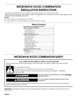
MICROWAVE HOOD COMBINATION
INSTALLATION INSTRUCTIONS
MICROWAVE HOOD COMBINATION SAFETY
This product is suitable for use above electric or gas cooking products up to 36" (91.4 cm) wide.
These installation instructions cover different models. The appearance of your particular model may differ slightly from the
illustration in these installation instructions.
NOTES:
■
Proper installation is the responsibility of the installer.
■
Product failure due to improper installation is not covered under the warranty.
Table of Contents
MICROWAVE HOOD COMBINATION SAFETY
..............................
1
INSTALLATION REQUIREMENTS
...................................................
2
Tools and Parts
...............................................................................
2
Location Requirements
...................................................................
2
Product Dimensions
.......................................................................
3
Electrical Requirements
..................................................................
3
INSTALLATION INSTRUCTIONS
.....................................................
4
Remove Mounting Plate
.................................................................
4
Rotate Blower Motor
.......................................................................
4
Locate Wall Stud(s)
.........................................................................
6
Mark Rear Wall
................................................................................
7
Drill Holes in Rear Wall
....................................................................
7
Attach Mounting Plate to Wall
........................................................
8
Prepare Upper Cabinet
...................................................................
8
Install Damper Assembly
................................................................
9
Install the Microwave Oven
............................................................
9
Complete Installation
....................................................................
10
VENTING DESIGN SPECIFICATIONS
............................................
11
ASSISTANCE
...................................................................................
12
Replacement Parts
.......................................................................
12
Accessories
...................................................................................
12
IMPORTANT:
Read Installation Instructions thoroughly before beginning installation. Save Installation Instructions for local house
inspector’s use.
8206587
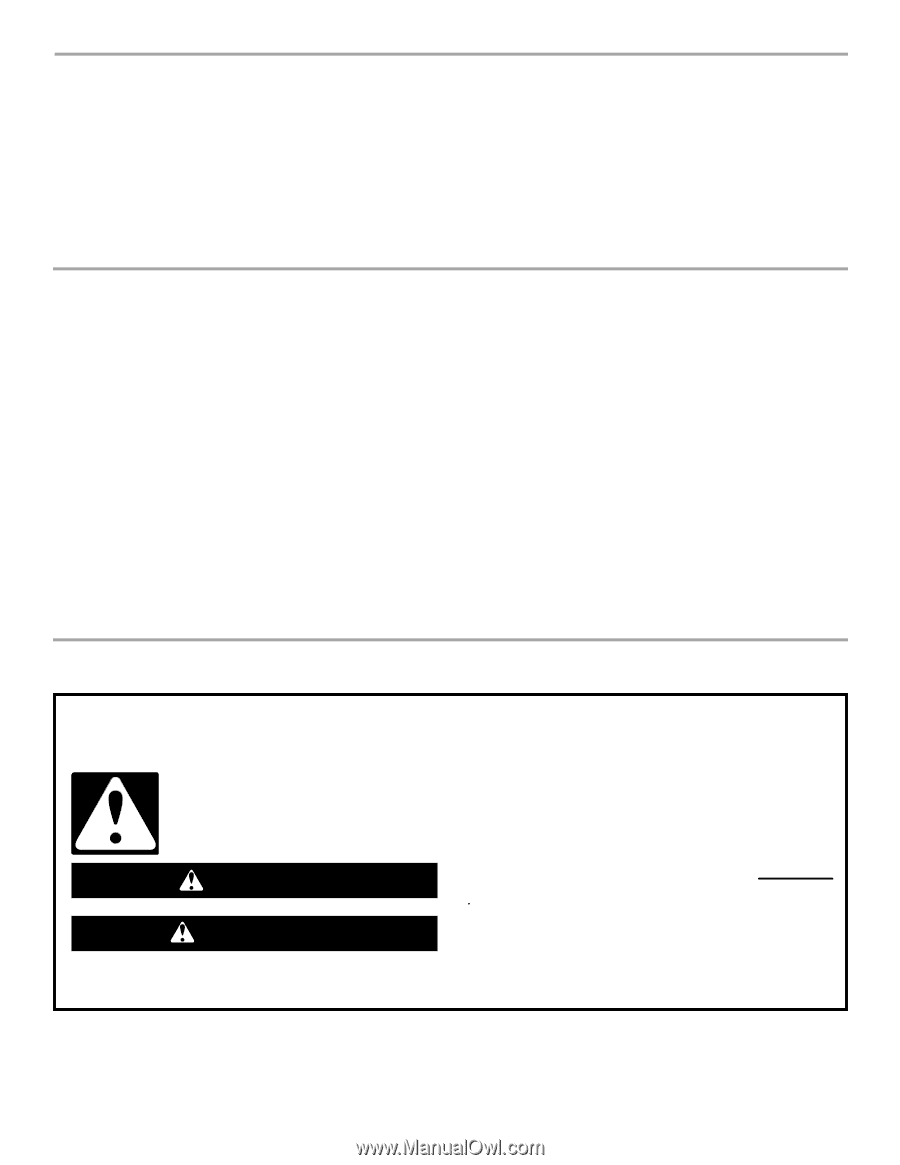
You can be killed or seriously injured if you don't immediately
You
can be killed or seriously injured if you don't follow
All safety messages will tell you what the potential hazard is, tell you how to reduce the chance of injury, and tell you what can
happen if the instructions are not followed.
Your safety and the safety of others are very important.
We have provided many important safety messages in this manual and on your appliance. Always read and obey all safety
messages.
This is the safety alert symbol.
This symbol alerts you to potential hazards that can kill or hurt you and others.
All safety messages will follow the safety alert symbol and either the word “DANGER” or “WARNING.”
These words mean:
follow instructions.
instructions.
DANGER
WARNING