Whirlpool SF367LXSS Installation Instructions
Whirlpool SF367LXSS Manual
 |
View all Whirlpool SF367LXSS manuals
Add to My Manuals
Save this manual to your list of manuals |
Whirlpool SF367LXSS manual content summary:
- Whirlpool SF367LXSS | Installation Instructions - Page 1
3 Tools and Parts 3 Location Requirements 3 Electrical Requirements 5 Gas Supply Requirements 5 INSTALLATION INSTRUCTIONS 7 Unpack Range 7 Install Anti-Tip Bracket 7 Verify Anti-Tip Bracket Location 8 Level Range 8 Make Gas Connection 9 Electronic Ignition System 10 Replace Oven Racks and - Whirlpool SF367LXSS | Installation Instructions - Page 2
building. • Immediately call your gas supplier from a neighbor's phone. Follow the gas supplier's instructions. • If you cannot reach your gas supplier, call the fire department. - Installation and service must be performed by a qualified installer, service agency or the gas supplier. In the State - Whirlpool SF367LXSS | Installation Instructions - Page 3
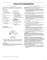
REQUIREMENTS Tools and Parts Gather the required tools and parts before starting installation. Read and follow the instructions provided with any tools the model/serial rating plate. The model/serial rating plate is located on the oven frame behind the storage drawer panel. ■ The range should - Whirlpool SF367LXSS | Installation Instructions - Page 4
depth, 24" (61 cm) base cabinet depth and 36" (91.4 cm) countertop height. If the cabinet depth is greater than 24" (61 cm), oven frame must extend beyond cabinet fronts by ½" (13 mm) metal cabinet. If installing a hood above the range, follow the hood instructions for dimensional clearances above the - Whirlpool SF367LXSS | Installation Instructions - Page 5
metal chassis of the range must be grounded in order for the control panel to work. If the metal chassis of the range is not grounded, no gas or, after proper conversion, for use with LP gas. ■ This range is factory set for use with Natural gas. See "Gas Conversions" section. The model/serial rating - Whirlpool SF367LXSS | Installation Instructions - Page 6
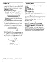
gas: Minimum pressure: 11" WCP Maximum pressure: 14" WCP Contact local gas supplier if you are not sure about the inlet pressure. Burner Input Requirements Input ratings shown on the model/serial rating range must be isolated from the gas supply piping system by closing its individual manual shutoff - Whirlpool SF367LXSS | Installation Instructions - Page 7
your type of floor covering. Before moving range, slide range onto shipping base, cardboard or hardboard. 1. Remove template from the anti-tip bracket kit (found inside the oven cavity) or from the back of this manual. 2. Place template on the floor in cabinet opening so that the left edge is - Whirlpool SF367LXSS | Installation Instructions - Page 8
white wheels in drawer guides. Remove drawer and set it aside on a protected surface. See the Use and Care Guide for the model drawer removal. To mount 11. Continue installing your range using the following installation instructions. If range is not level, pull range forward until rear leveling - Whirlpool SF367LXSS | Installation Instructions - Page 9
caps and grates from parts package. Burner caps should be level when properly positioned. If burner caps are not properly positioned, surface burners will not light. Place burner grates over burners and caps. B A C A. Burner base B. Burner cap C. Burner grate WARNING A. Gas pressure regulator - Whirlpool SF367LXSS | Installation Instructions - Page 10
air in the gas line. If burners do not light properly: ■ Turn cooktop control knob to the "OFF" position. ■ Check that the range is plugged in from oven and place the cover on a protected surface. A Adjust Flame Height Adjust the height of top burner flames. The cooktop "low" burner flame should - Whirlpool SF367LXSS | Installation Instructions - Page 11
Care" section of the Use and Care Guide. 6. Read "Range Use" in the Use and Care Guide. 7. Plug into a grounded 3 prong outlet. 8. Turn on surface burners and oven. See the Use and Care Guide for specific instruction on range operation. If range does not operate, check the following: ■ Household - Whirlpool SF367LXSS | Installation Instructions - Page 12
to follow these instructions can result in death or serious burns to children and adults. To Convert Gas Pressure Regulator 1. Turn the manual shutoff valve to the closed position. Unplug range or disconnect power. B A C A. To range B. Manual shutoff valve "closed" position C. Gas supply line 12 - Whirlpool SF367LXSS | Installation Instructions - Page 13
not made. See "Adjust Oven Broil Burner Flame" section. A A. Groove Refer to the following chart for correct LP gas orifice spud placement. LP Gas Orifice Spud Chart for Standard Surface Burners Burner Rating Color Size ID Number 12,000 BTU 11,000 BTU 8,000 BTU 5,000 BTU Green/Magenta Green - Whirlpool SF367LXSS | Installation Instructions - Page 14
as distinct as the inner cone. LP gas flames have a slightly yellow tip. 3. Refer to "Complete Installation" in the "Installation Instructions" section of this manual to complete this procedure. Convert from LP Gas to Natural Gas WARNING NOTE: On models with a warming drawer, an access cover must - Whirlpool SF367LXSS | Installation Instructions - Page 15
"Adjust Oven Broil Burner Flame" section. XXX A A. Stamped number Refer to the following chart for the correct Natural gas orifice spud placement. Natural Gas Orifice Spud Chart for Standard Surface Burners Burner Rating Color Size ID Number 13,500 BTU 12,000/12,500 BTU 9,500 BTU 8,000 BTU - Whirlpool SF367LXSS | Installation Instructions - Page 16
et ce qui peut se produire en cas de non-respect des instructions. AVERTISSEMENT : Pour votre sécurité, les renseignements dans ce manuel doivent doivent être effectués par un installateur qualifié, une agence de service ou le fournisseur de gaz. AVERTISSEMENT Risque de basculement Un enfant - Whirlpool SF367LXSS | Installation Instructions - Page 17
les outils et le matériel nécessaires. Lire et suivre les instructions fournies avec les outils indiqués ici. Outillage nécessaire ■ Mètre qualifié, qui pourra déterminer si le revêtement de sol peut résister à une température d'au moins 200°F (93°C). ■ Dans le cas de l'installation de la cuisini - Whirlpool SF367LXSS | Installation Instructions - Page 18
Title 24 CFR, Part 3280 (anciennement Federal Standard for Mobile Home Construction and Safety, Title 24, HUD Part 280). Lorsque cette d'une hotte au-dessus de la cuisinière, suivre les instructions fournies avec la hotte concernant les dimensions de dégagement à respecter au-dessus de la - Whirlpool SF367LXSS | Installation Instructions - Page 19
adaptateur. Ne pas utiliser un câble de rallonge. Le non-respect de ces instructions peut causer un décès, un incendie ou un choc électrique. IMPORTANT : La de la plus récente édition du code national en vigueur : National Fuel Gas Code ANSI Z223.1 (American National Standard), ou CAN/CGA B149. Type - Whirlpool SF367LXSS | Installation Instructions - Page 20
Canalisation de gaz Installer une canalisation de gaz rigide de ¾" (1,9 cm) jusqu'à l'emplacement d'installation de la cuisinière. L'emploi d'une canalisation de plus petit diamètre ou plus longue peut susciter une déficience du débit d'alimentation. On doit utiliser un composé d'étanchéité des - Whirlpool SF367LXSS | Installation Instructions - Page 21
pour déplacer et installer la cuisinière. Le non-respect de cette instruction peut causer une blessure au dos ou d'autre blessure. 1. Ôter les mat antibasculement si la cuisinière est déplacée. Le non-respect de ces instructions peut causer un décès ou des brûlures graves aux enfants et aux adultes - Whirlpool SF367LXSS | Installation Instructions - Page 22
Retirer le tiroir et le poser sur une surface protégée. Voir le Guide d'utilisation et d'entretien pour l'enlèvement du tiroir modèle. Pour emplacement". 11. Poursuivre l'installation de la cuisinière en utilisant les instructions d'installation suivantes. Si la cuisinière n'est pas d'aplomb, tirer - Whirlpool SF367LXSS | Installation Instructions - Page 23
pas enlever la broche de liaison à la terre. Ne pas utiliser un adaptateur. Ne pas utiliser un câble de rallonge. Le non-respect de ces instructions peut causer un décès, un incendie ou un choc électrique. 5. Brancher sur une prise à 3 alvéoles reliée à la terre. 23 - Whirlpool SF367LXSS | Installation Instructions - Page 24
Système d'allumage électronique Allumage initial et réglages des flammes Un système d'allumage électronique est utilisé à la place des flammes de veille usuelles pour l'allumage des brûleurs (table de cuisson et four). Lorsqu'on place le bouton de commande d'un brûleur de la table de cuisson à la - Whirlpool SF367LXSS | Installation Instructions - Page 25
ne survenir qu'après 50 à 60 secondes. Un dispositif d'allumage électronique est utilisé pour l'allumage des brûleurs du four et du gril. Consulter le Guide d'utilisation et d'entretien pour le bon fonctionnement des commandes du four. Réglage de la taille des flammes sur le brûleur du four (le cas - Whirlpool SF367LXSS | Installation Instructions - Page 26
terre. 8. Mettre en marche les brûleurs de la table de cuisson et le brûleur du four. Pour des instructions spécifiques concernant l'utilisation de la cuisinière, consulter le Guide d'utilisation et d'entretien. Si la cuisinière ne fonctionne pas, contrôler ce qui suit : ■ Fusible grillé ou desserr - Whirlpool SF367LXSS | Installation Instructions - Page 27
-écrou durant l'extraction. Appuyer pour engager le tourne-écrou sur le gicleur; faire tourner le gicleur dans le sens antihoraire puis soulever pour l'enlever. Conserver à part le gicleur du brûleur. C A D B A. Gicleur B. Porte-gicleur C. Vis D. Électrode d'allumage 27 - Whirlpool SF367LXSS | Installation Instructions - Page 28
de cuisson Puissance thermique Couleur Taille Code d'identification 12 000 BTU 11 000 BTU 8 000 BTU 5 000 BTU Vert/magenta Vert/jaune Vert/bleu clair Vert/marron 1,03 Achever l'installation" de la section "Instructions d'installation" du présent manuel pour la fin du processus d'installation. - Whirlpool SF367LXSS | Installation Instructions - Page 29
bride antibasculement si la cuisinière est déplacée. Le non-respect de ces instructions peut causer un décès ou des brûlures graves aux enfants et aux adultes tourner dans le sens antihoraire et soulever pour enlever le gicleur. Conserver à part le gicleur du brûleur. C A D A. Détendeur IMPORTANT : - Whirlpool SF367LXSS | Installation Instructions - Page 30
thermique Couleur Taille Code d'identification 13 500 BTU 12 000/12 500 BTU 9 500 BTU 8 000 BTU 5 000 BTU Bleu/orange Bleu/rouge Bleu/laiton Bleu/noir 3. Voir la section "Achever l'installation" dans la section "Instructions d'installation" du présent manuel pour achever l'installation. A. - Whirlpool SF367LXSS | Installation Instructions - Page 31
Notes 31 - Whirlpool SF367LXSS | Installation Instructions - Page 32
the left edge against the left side cabinet and the top edge against the rear wall template to anchor the left rear leg of range. Utiliser ce gabarit pour ancrer le pied arrière 2005 Whirlpool Corporation. All rights reserved. ® Registered Trademark/TM Trademark of Whirlpool, U.S.A., Whirlpool
-
 1
1 -
 2
2 -
 3
3 -
 4
4 -
 5
5 -
 6
6 -
 7
7 -
8
-
9
-
10
-
11
-
12
-
13
-
14
-
15
-
16
-
17
-
18
-
19
-
20
-
21
-
22
-
23
-
24
-
25
-
26
-
27
-
28
-
29
-
30
-
31
-
32
 |
 |

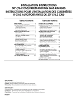
INSTALLATION INSTRUCTIONS
30" (76.2 CM) FREESTANDING GAS RANGES
INSTRUCTIONS POUR L’INSTALLATION DES CUISINIÈRES
À GAZ AUTOPORTANTES DE 30" (76,2 CM)
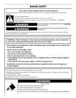
Table of Contents
Table des matières
RANGE SAFETY
...............................................
2
INSTALLATION REQUIREMENTS
..................
3
Tools and Parts
.............................................
3
Location Requirements
.................................
3
Electrical Requirements
................................
5
Gas Supply Requirements
............................
5
INSTALLATION INSTRUCTIONS
....................
7
Unpack Range
...............................................
7
Install Anti-Tip Bracket
..................................
7
Verify Anti-Tip Bracket Location
...................
8
Level Range
...................................................
8
Make Gas Connection
..................................
9
Electronic Ignition System
..........................
10
Replace Oven Racks and
Storage or Warming Drawer
.......................
11
Complete Installation
..................................
11
GAS CONVERSIONS
.....................................
12
Convert from Natural Gas to LP Gas
..........
12
Replace Oven Racks and
Storage or Warming Drawer
.......................
13
Complete Installation
..................................
14
Convert from LP Gas to Natural Gas
..........
14
Replace Oven Racks and
Storage or Warming Drawer
.......................
15
Complete Installation
..................................
15
ANTI-TIP BRACKET TEMPLATE
.................
32
SÉCURITÉ DE LA CUISINIÈRE
.....................
16
EXIGENCES D’INSTALLATION
.....................
17
Outillage et pièces
.......................................
17
Emplacement d’installation
.........................
17
Spécifications électriques
............................
19
Spécifications de l’alimentation en gaz
.......
19
INSTRUCTIONS D’INSTALLATION
..............
21
Déballage de la cuisinière
............................
21
Installation de la bride antibasculement
......
21
Vérification de l'emplacement
de la bride antibasculement
........................
22
Mise à niveau de la cuisinière
......................
22
Raccordement à la canalisation de gaz
......
23
Système d'allumage électronique
...............
24
Réinstallation des grilles du four et du
tiroir de remisage ou du tiroir-réchaud
.......
26
Achever l’installation
....................................
26
CONVERSIONS POUR
CHANGEMENT DE GAZ
................................
26
Conversion de Gaz naturel à Propane
........
26
Réinstallation des grilles du four et du
tiroir de remisage ou du tiroir-réchaud
........
28
Achever l'installation
....................................
28
Conversion de Propane à Gaz naturel
........
29
Réinstallation des grilles du four et du
tiroir de remisage ou du tiroir-réchaud
.......
30
Achever l'installation
....................................
30
GABARIT POUR LA BRIDE
ANTIBASCULEMENT
....................................
32
IMPORTANT:
Save for local electrical inspector's use.
Installer:
Leave installation instructions with the homeowner.
Homeowner:
Keep installation instructions for future reference.
IMPORTANT :
À conserver pour consultation par l'inspecteur local des installations électriques.
Installateur :
Remettre les instructions d'installation au propriétaire.
Propriétaire :
Conserver les instructions d'installation pour référence ultérieure.
9762997