Whirlpool WED7300XW Dimension Guide
Whirlpool WED7300XW Manual
 |
UPC - 883049202747
View all Whirlpool WED7300XW manuals
Add to My Manuals
Save this manual to your list of manuals |
Whirlpool WED7300XW manual content summary:
- Whirlpool WED7300XW | Dimension Guide - Page 1
Dryer PRODUCT MODEL NUMBERS WED6200S, WED6400S, WED6600V, WED6600W, WED7300X, WED7400X, WED7600X, WED7800X Dryer dimensions OVERALL DIMENSIONS Electrical: This dryer requires a 3 or 4 wire, single phase, 120/240 volt, 60 Hz., AC only electrical supply (or 3 or 4 wire, 120/208 volt electrical
-
 1
1
 |
 |
Electric Dryer
PRODUCT MODEL NUMBERS
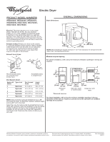
OVERALL DIMENSIONS
WED6200S, WED6400S, WED6600V,
WED6600W, WED7300X, WED7400X,
WED7600X, WED7800X
Electrical
:
This dryer requires a 3 or 4 wire, single
phase, 120/240 volt, 60 Hz., AC only electrical
supply (or 3 or 4 wire, 120/208 volt electrical supply,
if specified on the serial/rating plate) on a separate
30-amp circuit, fused on both sides of the line. A time-
delay fuse or circuit breaker is recommended. Connect
to an individual branch circuit. Do not have a fuse in the
neutral or grounding circuit.
Exhaust venting
:
Exhaust your dryer to the outside.
4" (102 mm) diameter vent is required. Rigid or flexible
metal exhaust vent must be used. Do not use plastic
or metal foil vent. Exhaust hood must be at least
12" (305 mm) from the ground or any object that
may be in the path of the exhaust.
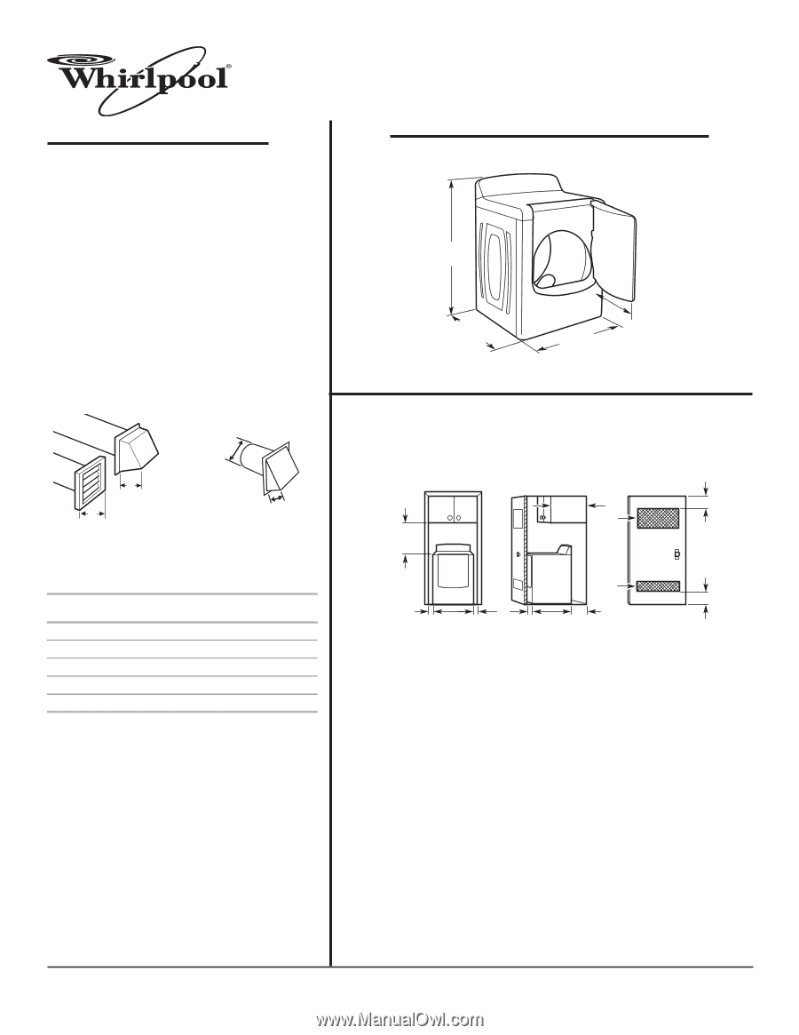
Exhaust hood styles
:
Vent System Chart
:
Dryer dimensions
Select the route that will provide the straightest and most
direct path outdoors. Plan the installation to use the fewest
number of elbows and turns. Use the fewest 90° turns
possible. Do not use vent runs longer than specified in
vent length chart. Determine the number of elbows you
will need.
Because Whirlpool Corporation policy includes a continuous commitment to improve
Dimensions are for planning purposes only. For complete details, see Installation
our products, we reserve the right to change materials and specifications without notice.
Instructions packed with product. Specifications subject to change without notice.
Ref. W10267633A
04/2010
For closet installation, with a door, the minimum ventilation openings in the top
and bottom of the door are required. Louvered doors with equivalent air ventilation
openings are acceptable.
For cabinet installation, with a door, the minimum ventilation openings in the top are
required.
NOTE:
Side and bottom exhaust installations have a 90°
turn inside the dryer. To determine maximum exhaust length,
add one 90° turn to the chart.
4"
(102 mm)
4"
(102 mm)
B
A
4"
(102 mm)
2½"
(64 mm)
C
Recommended styles:
A. Louvered hood
B. Box hood
Acceptable styles:
C. Angled hood
Number 90º
elbows
Type of vent
Box /louvered
hoods
Angled
hoods
0
Rigid metal
64 ft. (20 m)
58ft. (17.7 m)
1
Rigid metal
54 ft. (16.5 m)
48 ft. (14.6 m)
2
Rigid metal
44 ft. (13.4 m)
38 ft. (11.6 m)
3
Rigid metal
35 ft. (10.7 m)
29 ft. (8.8 m)
4
Rigid metal
27 ft. (8.2 m)
21 ft. (6.4 m)
Minimum required spacing
29"
(737 mm)
22
1
/
4
"
(565 mm)
29
1
/
4
"
(743 mm)
43
1
/
2
"
(1105 mm)
14" máx.*
(356 mm)
29"
(737 mm)
5"
(127 mm)
1"
(25 mm)
1"
(25 mm)
18"*
(457 mm)
3"*
(76 mm)
3"*
(76 mm)
29
1
/
4
"
(743 mm)
48"
2
*
(310 cm
2
)
24"
2
*
(155 cm
2
)
Recessed
area
Side view- closet
or confined area
Closet door with
vents
*Required spacing
NOTE:
Most installations require minimum 5" (127 mm) clearance for exhaust vent with
elbow. See “Venting Requirements.”