Whirlpool WED7505F Dimension Guide
Whirlpool WED7505F Manual
 |
View all Whirlpool WED7505F manuals
Add to My Manuals
Save this manual to your list of manuals |
Whirlpool WED7505F manual content summary:
- Whirlpool WED7505F | Dimension Guide - Page 1
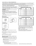
installation All dimensions show recommended and minimum spacing allowed. ■■ Additional spacing should be considered for ease of installation and servicing. ■■ Additional clearances might be required for wall, door, floor moldings, and dryer venting. ■■ Additional spacing should be considered on - Whirlpool WED7505F | Dimension Guide - Page 2
improve our products, we reserve the right to change materials and specifications without notice. Dimensions are for planning purposes only. For complete details, see Installation Instructions packed with product. Specifications subject to change without notice.
-
 1
1 -
 2
2
 |
 |
Electric Dryer
PRODUCT MODEL NUMBERS
W10868947A
10/2016
WED7505F, WED75HEF, WED7740F, WED77HEF, WED8540F,
WED85HEF, WED90HEF, WED92HEF
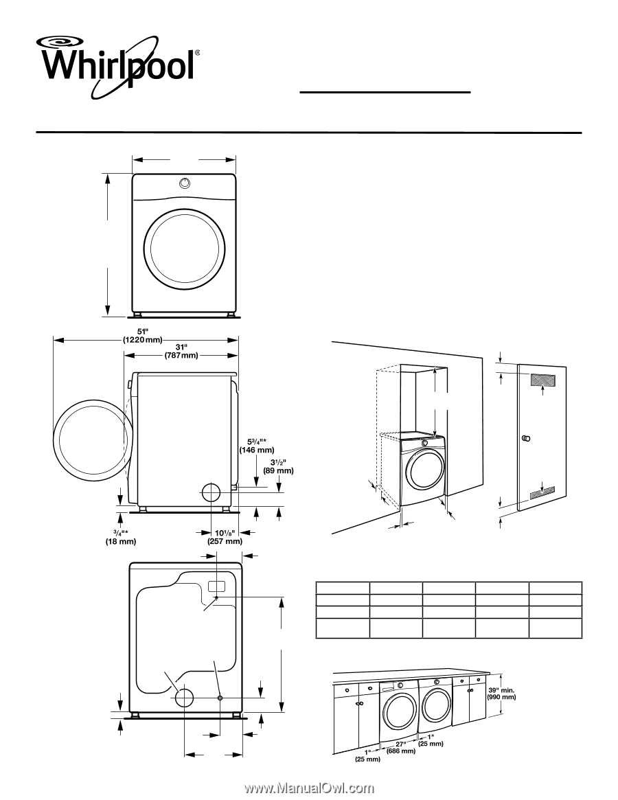
Dryer Dimensions
27"
(686 mm)
38
3
/
4
" Min.
(984 mm)
39" Max.
(990 mm)
Front view:
Side view:
Installation spacing for recessed area or closet
installation
All dimensions show recommended and minimum spacing
allowed.
■
Additional spacing should be considered for ease of
installation and servicing.
■
Additional clearances might be required for wall, door,
floor moldings, and dryer venting.
■
Additional spacing should be considered on all sides
of the dryer to reduce noise transfer.
■
For closet installation with a door, minimum ventilation
openings in the top and bottom of the door are required.
Louvered doors with equivalent ventilation openings are
acceptable.
■
Companion appliance spacing should also be considered.
Back view:
6
1
/
2
"
(165 mm)
29
7
/
8
"*
(759 mm)
3
1
/
2
"*
(89 mm)
6
1
/
8
"*
(156 mm)
14
3
/
8
"
(365 mm)
3
/
4
"*
(18 mm)
NOTE:
Most
installations
require a minimum
of 5" (127 mm)
clearance behind
dryer for exhaust
vent with elbow.
See “Venting
Requirements.”
*Approx. measurement.
Power supply
cord/cable
Water inlet
(Steam
models
only)
Vent
Recommended installation clearances (dryer only):
*0" (0 mm) spacing is allowed for straight-back venting only.
For steam models only, inlet hose must not be kinked.
Front
Sides
Rear
Top
Recessed
NA
0" (0 mm)
0" (0 mm)**
0" (0 mm)
Closet
NA
0" (0 mm)
0" (0 mm)**
0" (0 mm)
Under
Counter
NA
1” (25 mm)
0” (0 mm)**
0” (0 mm)
Minimum installation clearances (dryer only):
**0
"
(0 mm) spacing is allowed for straight-back venting only.
18" min.
(457 mm)
1"*
(25 mm)
0" - 5"*
(0" - 127 mm)
24 in.
2
min.
(155 cm
2
)
48 in.
2
min.
(310 cm
2
)
3"
(76 mm)
3"
(76 mm)
1"
(25 mm)
0
"
–5"*
(0 mm–127 mm)
Custom under counter installation: