Whirlpool WED9470WW Installation Instructions
Whirlpool WED9470WW Manual
 |
View all Whirlpool WED9470WW manuals
Add to My Manuals
Save this manual to your list of manuals |
Whirlpool WED9470WW manual content summary:
- Whirlpool WED9470WW | Installation Instructions - Page 1
INSTALL LEVELING LEGS 13 CONNECT VENT 14 CONNECT INLET HOSE (STEAM MODELS 14 LEVEL DRYER 15 COMPLETE INSTALLATION 15 TROUBLESHOOTING 15 DRYER SAFETY Your safety and the safety of others are very important. We have provided many important safety messages in this manual and on your appliance - Whirlpool WED9470WW | Installation Instructions - Page 2
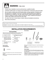
exhaust vent) ■ Tin snips (new vent installations) ■ ¼" nut driver (recommended) ■ Tape measure ■ Pliers Parts supplied Non-Steam Models Steam Models A B C D E A. Leveling legs (4) B. "Y" connector C. Short inlet hose D. Long inlet hose E. Rubber washer Remove parts package from dryer drum - Whirlpool WED9470WW | Installation Instructions - Page 3
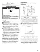
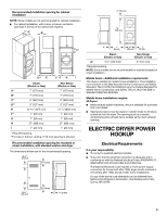
floor. If using a pedestal, you will need 18" (460 mm) to the bottom of the dryer. ■ Steam models only: Cold water faucets located within 4 ft (1.2 m) of the dryer, and water pressure of 20-100 psi (137.9-689.6 kPa). You may use the cold water supply from your washer using the "Y" connector provided - Whirlpool WED9470WW | Installation Instructions - Page 4
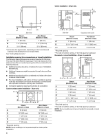
door with vents Steam (Electric or Gas) Non-Steam (Electric or Gas) A* 1" (25 mm) 1" (25 mm) B 32 9/16" (827 mm) 31 1/2" (800 mm) C** 5" (127 mm) 5" (127 mm) *Required spacing **For side or bottom venting, 0" (0 mm) spacing is allowed. Recessed or closet installation - Dryer on pedestal - Whirlpool WED9470WW | Installation Instructions - Page 5
686 mm) I 1" (25 mm) 1" (25 mm) *Required spacing **For side or bottom venting, 0" (0 mm) spacing is allowed. Recommended installation spacing for recessed or closet installation, with stacked washer and dryer The dimensions shown are for the recommended spacing. 48 in.2 * (310 cm2) 3"* (76 mm - Whirlpool WED9470WW | Installation Instructions - Page 6
dryers. The kit should contain: ■ A UL listed 30-amp power supply cord, rated 120/240 volt minimum. The cord should be type SRD or SRDT and be at least 4 ft (1.22 m) long. The wires that connect to the dryer supply cord, at least 4 ft (1.22 m) long, must have four 10-gauge copper wires and match - Whirlpool WED9470WW | Installation Instructions - Page 7
Be sure that the wire insulation on the power supply cord is inside the strain relief. The strain relief should have a tight fit with the dryer cabinet and be in a horizontal position. Do not further tighten strain relief screws at this point. Style 2: Direct wire strain relief WARNING Fire Hazard - Whirlpool WED9470WW | Installation Instructions - Page 8
3-wire connections. A B F 4. Now complete installation following instructions for your type of electrical connection: 4-wire (recommended) 3-wire NEMA Type 14-30R) A UL listed, 120/ 240-volt minimum, 30-amp, dryer power supply cord* 4-wire connection: Power supply cord 4-wire direct 5" (127 mm - Whirlpool WED9470WW | Installation Instructions - Page 9
connection. Now go to "Venting Requirements." 4-wire connection: Direct wire IMPORTANT: A 4-wire connection is required for mobile homes and where local codes do not permit the use of 3-wire connections. Direct wire cable must have 5 ft (1.52 m) of extra length so dryer can be moved if needed - Whirlpool WED9470WW | Installation Instructions - Page 10
slot of dryer rear panel. Secure cover with hold-down screw. 7. You have completed your electrical connection. Now go to "Venting Requirements." cabinet-ground conductor to neutral wire. Direct wire cable must have 5 ft (1.52 m) of extra length so dryer can be moved if needed. Strip 31/2" (89 mm) of - Whirlpool WED9470WW | Installation Instructions - Page 11
mm) heavy metal exhaust vent Vent products can be purchased from your dealer or by calling Whirlpool Service. For more information, see the "Assistance or Service" section. Rigid metal vent ■ For best drying performance, rigid metal vents are recommended. ■ Rigid metal vent is recommended to avoid - Whirlpool WED9470WW | Installation Instructions - Page 12
vent must be fully extended and supported when the dryer is in its final location. ■ Remove excess flexible metal vent problems and health problems. Plan Vent System Choose your exhaust installation type Recommended exhaust installations Typical installations vent the dryer from the rear of the dryer - Whirlpool WED9470WW | Installation Instructions - Page 13
NOTE: The following kits for close-clearance alternate installations are available for purchase. Please see the "Assistance or Service" section to order. ■ Over-the-Top Installation: Part Number 4396028 ■ Periscope Installation (For use with dryer vent to wall vent mismatch): Part Number 4396037 - Whirlpool WED9470WW | Installation Instructions - Page 14
seated on fill valve connector. CONNECT INLET HOSE (STEAM MODELS) The dryer must be connected to the cold water faucet using the new inlet hoses. Do not use old hoses. 1. Turn cold water faucet off and remove washer inlet hose. 2. Remove old rubber washer from inlet hose and replace with new rubber - Whirlpool WED9470WW | Installation Instructions - Page 15
, there may be a problem with your home power supply keeping the dryer's heater from turning on. See "Troubleshooting." 14. When the dryer has been running for 5 minutes, open the dryer door and feel for heat. If you feel heat, cancel cycle and close the door. If you do not feel heat, turn off the - Whirlpool WED9470WW | Installation Instructions - Page 16
at the top and bottom of the door. The front of the dryer requires a minimum of 1" (25 mm) of airspace, and, for most installations, the rear of the dryer requires 5" (127 mm). See the Installation Instructions. Fire Hazard Use a heavy metal vent. Do not use a plastic vent. Do not use a metal foil
-
 1
1 -
 2
2 -
 3
3 -
 4
4 -
 5
5 -
 6
6 -
 7
7 -
8
-
9
-
10
-
11
-
12
-
13
-
14
-
15
-
16
 |
 |
ELECTRIC DRYER INSTALLATION INSTRUCTIONS
U.S.A. ONLY
Para una versión de estas instrucciones en español, visite www.Whirlpool.com
TABLE OF CONTENTS
DRYER SAFETY
..............................................................................
1
INSTALLATION REQUIREMENTS
................................................
2
Tools and Parts
............................................................................
2
Optional Equipment
.....................................................................
3
Location Requirements
................................................................
3
ELECTRIC DRYER POWER HOOKUP
.........................................
5
Electrical Requirements
...............................................................
5
Electrical Connection
...................................................................
6
VENTING
.......................................................................................
11
Venting Requirements
................................................................
11
Plan Vent System
.......................................................................
12
Install Vent System
.....................................................................
13
INSTALL LEVELING LEGS
...........................................................
13
CONNECT VENT
...........................................................................
14
CONNECT INLET HOSE
(STEAM MODELS)
........................................................................
14
LEVEL DRYER
..............................................................................
15
COMPLETE INSTALLATION
.......................................................
15
TROUBLESHOOTING
..................................................................
15
W10255468C
W10259190B - SP
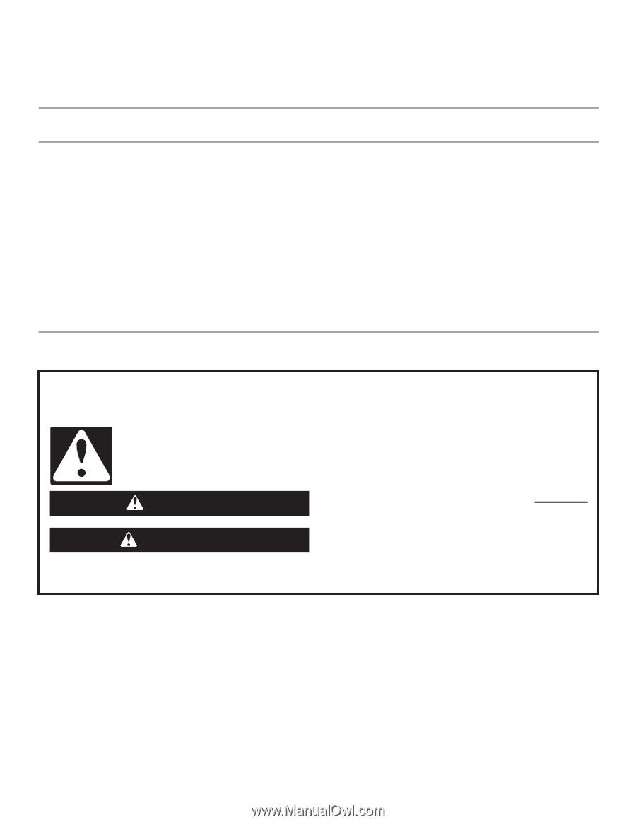
DRYER SAFETY
You
You can be killed or seriously injured if you don't immediately
can be killed or seriously injured if you don't
follow
All
s
afety me
ss
age
s
will tell you what the potential hazard i
s
, tell you how to reduce the chance of injury, and tell you what can
happen if the in
s
truction
s
are not followed.
Your safety and the safety of others are very important.
We have provided many important
s
afety me
ss
age
s
in thi
s
manual and on your appliance. Alway
s
read and obey all
s
afety
me
ss
age
s
.
Thi
s
i
s
the
s
afety alert
s
ymbol.
Thi
s
s
ymbol alert
s
you to potential hazard
s
that can kill or hurt you and other
s
.
All
s
afety me
ss
age
s
will follow the
s
afety alert
s
ymbol and either the word “DANGER” or “WARNING.”
The
s
e word
s
mean:
follow instructions.
instructions.
DANGER
WARNING