Whirlpool WFC310S0AT Installation Guide
Whirlpool WFC310S0AT Manual
 |
View all Whirlpool WFC310S0AT manuals
Add to My Manuals
Save this manual to your list of manuals |
Whirlpool WFC310S0AT manual content summary:
- Whirlpool WFC310S0AT | Installation Guide - Page 1
30" (76 CM) FREESTANDING ELECTRIC RANGES Table of Contents RANGE SAFETY 2 INSTALLATION REQUIREMENTS 3 Tools and Parts 3 Location Requirements 3 Electrical Requirements - U.S.A. Only 5 INSTALLATION INSTRUCTIONS 6 Unpack Range 6 Install Anti-Tip Bracket 6 Electrical Connection - U.S.A. Only - Whirlpool WFC310S0AT | Installation Guide - Page 2
RANGE SAFETY Your safety and the safety of others are very important. We have provided many important safety messages in this manual and on your appliance bracket if range is moved. Do not operate range without anti-tip bracket installed and engaged. Failure to follow these instructions can result - Whirlpool WFC310S0AT | Installation Guide - Page 3
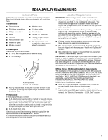
strap if necessary) Parts supplied Check that all parts are included. ■ model/serial rating plate. The model range is installed in a mobile home, it must be secured per the instructions in this document. ■ Four-wire power supply cord or cable must be used in a mobile home installation. The appliance - Whirlpool WFC310S0AT | Installation Guide - Page 4
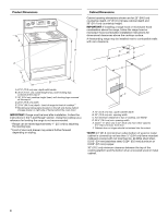
to front of cooktop** F. Model/serial rating plate (located on the left side frame behind storage drawer or right side of frame behind the oven door) IMPORTANT: Range must be level after installation. Follow the instructions in the "Level Range" section. Using the cooktop as a reference for leveling - Whirlpool WFC310S0AT | Installation Guide - Page 5
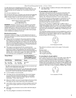
electrician or service technician if you are in doubt as to whether the appliance is properly and follow the instructions provided for it here. This range is manufactured with load is less than the total connected load listed on the model/serial rating plate. **If connecting to a 50-amp circuit, - Whirlpool WFC310S0AT | Installation Guide - Page 6
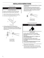
. C A 1. Remove shipping materials, tape and film from range. 2. Remove oven racks and parts package from inside oven. 3. Do not remove the shipping base can tip the range and be killed. Install anti-tip bracket to floor or wall per installation instructions. Slide range back so rear range foot is - Whirlpool WFC310S0AT | Installation Guide - Page 7
or hardboard from under range. 7. Move range into its final location, making sure rear leveling leg slides into anti-tip bracket. 8. Move range forward onto shipping base, cardboard or hardboard to continue installing the range using the following installation instructions. Rear position Front - Whirlpool WFC310S0AT | Installation Guide - Page 8
can result in death, fire, or electrical shock. Electrical Shock Hazard Disconnect power before servicing. Use 8 gauge copper or 6 gauge aluminum wire. Electrically ground range. Failure to follow these instructions can result in death, fire, or electrical shock. 1. Disconnect power. 2. Remove the - Whirlpool WFC310S0AT | Installation Guide - Page 9
conduit. 5. Complete installation following instructions for your type of electrical local codes prohibit grounding through the neutral 1. Part of metal ground strap must be cut out and to remove the ground-link screw from the back of the range. Save the ground-link screw and the end of the ground - Whirlpool WFC310S0AT | Installation Guide - Page 10
to neutral wire of power supply cord. 1. Feed the power supply cord through the strain relief on the cord/conduit plate on bottom of range. Allow enough slack to easily attach the wiring to the terminal block. A D B C A. 10-32 hex nut B. Line 2 (red) C. Ground-link screw D. Neutral (white) wire - Whirlpool WFC310S0AT | Installation Guide - Page 11
■ In an area where local codes prohibit grounding through the neutral 1. Part of metal ground strap must be cut out and removed. 4. Attach terminal a Phillips screwdriver to remove the ground-link screw from the back of the range. Save the ground-link screw and the end of the ground link under the - Whirlpool WFC310S0AT | Installation Guide - Page 12
if local codes permit connecting ground conductor to neutral supply wire. 1. Pull the wires through the conduit on cord/conduit plate on bottom of range. Allow enough slack to easily attach the wiring to the terminal block. A 3. Use ³⁄₈" nut driver to connect the bare (green) ground wire to the - Whirlpool WFC310S0AT | Installation Guide - Page 13
or Service" section of the Use and Care Guide, or the cover or "Warranty" section of the User Instructions, to contact service. Level Range Determine Drawer (on some models) Remove all items from inside the warming drawer or premium storage drawer, and allow the range to cool completely before - Whirlpool WFC310S0AT | Installation Guide - Page 14
glides on both sides. Storage Drawer (on some models) The storage drawer can be removed. Before removing, placed in the drawer. Oven Door For normal range use, it is not suggested to remove the sure the oven is off and cool. Then, follow these instructions. The oven door is heavy. To Remove: 1. Open - Whirlpool WFC310S0AT | Installation Guide - Page 15
to verify the electrical supply. ■ See the "Troubleshooting" section in the Use and Care Guide or User Instructions. When the range has been on for 5 minutes, check for heat. If range is cold, turn off the range and contact a qualified technician. Moving the Range WARNING Tip Over Hazard A child or - Whirlpool WFC310S0AT | Installation Guide - Page 16
W10403811B © 2011. All rights reserved. TM AQUALIFT is a trademark of Whirlpool, U.S.A. 12/11 Printed in U.S.A.
-
 1
1 -
 2
2 -
 3
3 -
 4
4 -
 5
5 -
 6
6 -
 7
7 -
8
-
9
-
10
-
11
-
12
-
13
-
14
-
15
-
16
 |
 |

INSTALLATION INSTRUCTIONS
30" (76 CM) FREESTANDING ELECTRIC RANGES
Table of Contents
RANGE SAFETY
.............................................................................
2
INSTALLATION REQUIREMENTS
................................................
3
Tools and Parts
............................................................................
3
Location Requirements
................................................................
3
Electrical Requirements - U.S.A. Only
.........................................
5
INSTALLATION INSTRUCTIONS
..................................................
6
Unpack Range
.............................................................................
6
Install Anti-Tip Bracket
.................................................................
6
Electrical Connection - U.S.A. Only
.............................................
8
Verify Anti-Tip Bracket Is Installed and Engaged
......................
12
Level Range
...............................................................................
13
Warming Drawer or Premium Storage Drawer
..........................
13
Storage Drawer
..........................................................................
14
Oven Door
..................................................................................
14
Complete Installation
.................................................................
15
Moving the Range
......................................................................
15
IMPORTANT:
Save for local electrical inspector's use.
W10403811B