Whirlpool WFE374LVB Installation Instructions
Whirlpool WFE374LVB Manual
 |
View all Whirlpool WFE374LVB manuals
Add to My Manuals
Save this manual to your list of manuals |
Whirlpool WFE374LVB manual content summary:
- Whirlpool WFE374LVB | Installation Instructions - Page 1
INSTALLATION INSTRUCTIONS 30" (76 CM) FREESTANDING ELECTRIC RANGES Table of Contents RANGE SAFETY 2 INSTALLATION REQUIREMENTS 3 Tools and Parts 3 Location Requirements 3 Electrical Requirements - U.S.A. Only 4 INSTALLATION INSTRUCTIONS 6 Unpack Range 6 Install Anti-Tip Bracket 6 Electrical - Whirlpool WFE374LVB | Installation Instructions - Page 2
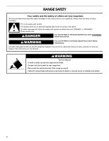
RANGE SAFETY Your safety and the safety of others are very important. We have provided many important safety messages in this manual and the range and be killed. Connect anti-tip bracket to rear range foot. Reconnect the anti-tip bracket, if the range is moved. Failure to follow these instructions - Whirlpool WFE374LVB | Installation Instructions - Page 3
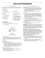
REQUIREMENTS Tools and Parts Gather the required tools and parts before starting installation. Read and follow the instructions provided with any tools listed here. Tools needed ■ Tape measure ■ ¼" drive ratchet ■ Flat-blade screwdriver ■ Level ■ Hammer ■ Hand or electric drill ■ Wrench or - Whirlpool WFE374LVB | Installation Instructions - Page 4
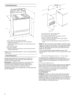
range hood or microwave hood combination above the range, follow the range hood or microwave hood combination installation instructions for dimensional clearances above the cooktop surface. A freestanding range a risk of electric shock. Check with a qualified electrician or service technician if you - Whirlpool WFE374LVB | Installation Instructions - Page 5
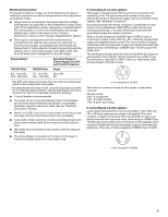
be using and follow the instructions provided for it here. ■ Range must be connected to the proper electrical voltage and frequency as specified on the model/serial number rating plate. The model/serial number rating plate is located behind the control panel or on the oven frame behind the storage - Whirlpool WFE374LVB | Installation Instructions - Page 6
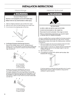
in back or other injury. 1. Remove shipping materials, tape and film from range. 2. Remove oven racks and parts package from inside oven. 3. Do not remove the shipping base at this time. A A. Shipping base 4. On Ranges Equipped with Storage Drawers: Remove the storage drawer. See the "Storage Drawer - Whirlpool WFE374LVB | Installation Instructions - Page 7
grounded outlet. Failure to follow these instructions can result in death, fire, or electrical shock. Electrical Shock Hazard Disconnect power before servicing. Use 8 gauge copper or 6 gauge aluminum wire. Electrically ground range. Failure to follow these instructions can result in death, fire, or - Whirlpool WFE374LVB | Installation Instructions - Page 8
(NEMA type 14-50R) A UL listed, 250-volt minimum, 40-amp, range power supply cord 4-wire connection: Power supply cord A A. UL listed strain 1. Part of metal ground strap must be cut out and removed. A B C 5. Complete installation following instructions for your type of electrical connection - Whirlpool WFE374LVB | Installation Instructions - Page 9
UL listed strain relief D. Power supply cord wires 4. Use a Phillips screwdriver to connect the green ground wire from the power supply cord to the range with the ground-link screw and ground-link section. The ground wire must be attached first. 5. Use ³⁄₈" nut driver to connect the neutral (white - Whirlpool WFE374LVB | Installation Instructions - Page 10
-link screw from the back of the range. Save the ground-link screw and the end of the ground-link under the screw. C D E A. Terminal lug B. Setscrew C. Line 2 (red) wire D. Neutral (white) wire E. Line 1 (black) wire Bare Wire Torque Specifications Attaching terminal lugs to the terminal block - Whirlpool WFE374LVB | Installation Instructions - Page 11
the wires through the conduit on cord/conduit plate on bottom of range. Allow enough slack to easily attach the wiring to the terminal D. Bare (green) ground wire E. Line 1 (black) wire Bare Wire Torque Specifications Attaching terminal lugs to the terminal block - 20 lbs-in. (2.3 N-m) Wire Awg - Whirlpool WFE374LVB | Installation Instructions - Page 12
cm). It will be necessary to disengage the storage drawer one side at a time. 2. Insert a flat-blade screwdriver through the opening in the side of anti-tip bracket. NOTE: Range must be level for satisfactory baking performance. 4. Replace the storage drawer (on some models). A. Drawer clip 3. - Whirlpool WFE374LVB | Installation Instructions - Page 13
and oven. See the Use and Care Guide for specific instruction on range operation. If range does not operate, check the following: ■ Household fuse is intact and tight; or circuit breaker has not tripped. ■ Range is plugged into an outlet. ■ Electrical supply is connected. ■ See "Troubleshooting" in - Whirlpool WFE374LVB | Installation Instructions - Page 14
-tip bracket is installed: ■ Look for the anti-tip bracket securely attached to floor. ■ Slide range back so rear range foot is under anti-tip bracket. Electrical Shock Hazard Disconnect power before servicing. Replace all parts and panels before operating. Failure to do so can result in death or - Whirlpool WFE374LVB | Installation Instructions - Page 15
Left edge ANTI-TIP BRACKET TEMPLATE Cut on dotted lines and place the left edge against the left side cabinet and the top edge against the rear wall. Top edge 15 - Whirlpool WFE374LVB | Installation Instructions - Page 16
W10252706B © 2009. All rights reserved. 9/09 Printed in U.S.A.
-
 1
1 -
 2
2 -
 3
3 -
 4
4 -
 5
5 -
 6
6 -
 7
7 -
8
-
9
-
10
-
11
-
12
-
13
-
14
-
15
-
16
 |
 |

INSTALLATION INSTRUCTIONS
30" (76 CM) FREESTANDING ELECTRIC RANGES
Table of Contents
RANGE SAFETY
...................................................................................
2
INSTALLATION REQUIREMENTS
......................................................
3
Tools and Parts
..................................................................................
3
Location Requirements
......................................................................
3
Electrical Requirements - U.S.A. Only
...............................................
4
INSTALLATION INSTRUCTIONS
........................................................
6
Unpack Range
....................................................................................
6
Install Anti-Tip Bracket
.......................................................................
6
Electrical Connection - U.S.A. Only
...................................................
7
Verify Anti-Tip Bracket Location
......................................................
12
Level Range
......................................................................................
12
Storage Drawer
................................................................................
12
Complete Installation
.......................................................................
13
Moving the Range
............................................................................
14
ANTI-TIP BRACKET TEMPLATE
.....................................................
15
IMPORTANT:
Save for local electrical inspector's use.
W10252706B