Whirlpool WFE524CLBB Installation Guide
Whirlpool WFE524CLBB Manual
 |
View all Whirlpool WFE524CLBB manuals
Add to My Manuals
Save this manual to your list of manuals |
Whirlpool WFE524CLBB manual content summary:
- Whirlpool WFE524CLBB | Installation Guide - Page 1
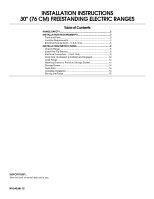
INSTALLATION INSTRUCTIONS 30" (76 CM) FREESTANDING ELECTRIC RANGES Table of Contents RANGE SAFETY 2 INSTALLATION REQUIREMENTS 3 Tools and Parts 3 Location Requirements 3 Electrical Requirements - U.S.A. Only 5 INSTALLATION INSTRUCTIONS 6 Unpack Range 6 Install Anti-Tip Bracket 6 Electrical - Whirlpool WFE524CLBB | Installation Guide - Page 2
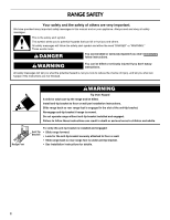
RANGE SAFETY Your safety and the safety of others are very important. We have provided many important safety messages in this manual anti-tip bracket if range is moved. Do not operate range without anti-tip bracket installed and engaged. Failure to follow these instructions can result in death - Whirlpool WFE524CLBB | Installation Guide - Page 3
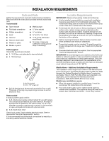
parts before starting installation. Read and follow the instructions provided with any tools listed here. Tools needed ■ Tape measure ■ Masking tape ■ Flat-blade screwdriver ■ ¼" drive ratchet ■ Phillips screwdriver ■ Level ■ Hammer ■ Hand or electric by installing a range hood that projects - Whirlpool WFE524CLBB | Installation Guide - Page 4
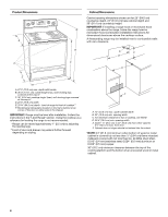
E. 25 64.3 cm) depth - back of range to front of cooktop** F. Model/serial rating plate (located on the frame behind a top corner of the door or either side of the drawer) IMPORTANT: Range must be level after installation. Follow the instructions in the "Level Range" section. Using the cooktop as - Whirlpool WFE524CLBB | Installation Guide - Page 5
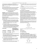
electrical connection you will be using and follow the instructions provided for it here. ■ Range must be connected to the proper electrical voltage and frequency as specified on the model/serial rating plate. The model range can be moved if servicing is ever necessary. 3-wire receptacle (10-50R) 5 - Whirlpool WFE524CLBB | Installation Guide - Page 6
INSTALLATION INSTRUCTIONS Unpack Range WARNING Excessive Weight Hazard Use two or more people to move and install range. Failure to do so can result in back or other injury. 1. Remove shipping materials, tape and film from range. 2. Remove oven racks and parts package from inside oven. 3. Do not - Whirlpool WFE524CLBB | Installation Guide - Page 7
Move range close enough to opening to allow for final electrical connections. Remove shipping base, cardboard or hardboard from under range. 7. Move range into range forward onto shipping base, cardboard or hardboard to continue installing the range using the following installation instructions. - Whirlpool WFE524CLBB | Installation Guide - Page 8
and toward you to remove cover from range. Electrical Shock Hazard Disconnect power before servicing. Use 8 gauge copper or 6 gauge aluminum wire. Electrically ground range. Failure to follow these instructions can result in death, fire, or electrical shock. Style 1: Power supply cord strain relief - Whirlpool WFE524CLBB | Installation Guide - Page 9
Part of metal ground strap must be cut out and removed. 5. Complete installation following instructions for your type of electrical power supply cord through the strain relief on the cord/conduit plate on bottom of range. Allow enough slack to easily attach the wiring to the terminal block. A B - Whirlpool WFE524CLBB | Installation Guide - Page 10
6. Replace terminal block access cover. Direct Wire Installation: Copper or Aluminum Wire This range may be connected directly to the fuse disconnect or circuit breaker box. Depending on your electrical supply, make the required 3-wire or 4-wire connection. 1. Strip outer covering back 3" (7.6 cm - Whirlpool WFE524CLBB | Installation Guide - Page 11
1. Part of metal ground strap must be cut out and removed. A B C A. Metal ground strap B. Discard C. Ground-link screw 2. Use a Phillips screwdriver to remove the ground-link screw from the back of the range. Save the ground-link screw and the end of the ground link under the screw. 3. Pull the - Whirlpool WFE524CLBB | Installation Guide - Page 12
. Slide the range forward and determine if there is an obstruction between the range and the mounting wall. If you need assistance or service, refer to the "Assistance or Service" section of the Use and Care Guide, or the cover or "Warranty" section of the User Instructions, for contact information - Whirlpool WFE524CLBB | Installation Guide - Page 13
Service" section of the Use and Care Guide, or the cover or "Warranty" section of the User Instructions, to contact service. Level Range Storage Drawer (on some models) Remove all items from inside the warming drawer or premium storage drawer, and allow the range to cool completely before attempting - Whirlpool WFE524CLBB | Installation Guide - Page 14
models Check that all parts are now installed. If there is an extra part, go back through electrical outlet in the home may be miswired. Contact a qualified electrician to verify the electrical supply. ■ See the "Troubleshooting" section in the Use and Care Guide or User Instructions. When the range - Whirlpool WFE524CLBB | Installation Guide - Page 15
instructions. Slide range back so rear range foot is engaged in the slot of the anti-tip bracket. Re-engage anti-tip bracket if range is moved. Do not operate range 6. Check that range is level. Electrical Shock Hazard Disconnect power before servicing. Replace all parts and panels before operating - Whirlpool WFE524CLBB | Installation Guide - Page 16
W10403811C ®/™ ©2012 Whirlpool. All rights reserved. 8/12 Printed in U.S.A.
-
 1
1 -
 2
2 -
 3
3 -
 4
4 -
 5
5 -
 6
6 -
 7
7 -
8
-
9
-
10
-
11
-
12
-
13
-
14
-
15
-
16
 |
 |

INSTALLATION INSTRUCTIONS
30" (76 CM) FREESTANDING ELECTRIC RANGES
Table of Contents
RANGE SAFETY
..................................................................................
2
INSTALLATION REQUIREMENTS
.....................................................
3
Tools and Parts
.................................................................................
3
Location Requirements
.....................................................................
3
Electrical Requirements - U.S.A. Only
..............................................
5
INSTALLATION INSTRUCTIONS
.......................................................
6
Unpack Range
..................................................................................
6
Install Anti-Tip Bracket
......................................................................
6
Electrical Connection - U.S.A. Only
..................................................
8
Verify Anti-Tip Bracket Is Installed and Engaged
...........................
12
Level Range
....................................................................................
13
Warming Drawer or Premium Storage Drawer
...............................
13
Storage Drawer
...............................................................................
14
Oven Door
.......................................................................................
14
Complete Installation
......................................................................
14
Moving the Range
...........................................................................
15
IMPORTANT:
Save for local electrical inspector's use.
W10403811C