Whirlpool WFE540H0AH Installation Guide
Whirlpool WFE540H0AH Manual
 |
View all Whirlpool WFE540H0AH manuals
Add to My Manuals
Save this manual to your list of manuals |
Whirlpool WFE540H0AH manual content summary:
- Whirlpool WFE540H0AH | Installation Guide - Page 1
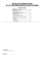
INSTALLATION INSTRUCTIONS 30" (76 CM) FREESTANDING ELECTRIC RANGES Table of Contents RANGE SAFETY 2 INSTALLATION REQUIREMENTS 3 Tools and Parts 3 Location Requirements 3 Electrical Requirements - U.S.A. Only 5 INSTALLATION INSTRUCTIONS 6 Unpack Range 6 Install Anti-Tip Bracket 6 Electrical - Whirlpool WFE540H0AH | Installation Guide - Page 2
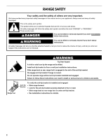
RANGE SAFETY Your safety and the safety of others are very important. We have provided many important safety messages in this manual anti-tip bracket if range is moved. Do not operate range without anti-tip bracket installed and engaged. Failure to follow these instructions can result in death - Whirlpool WFE540H0AH | Installation Guide - Page 3
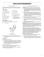
the required tools and parts before starting installation. Read and follow the instructions provided with any tools listed here. Tools needed ■ Tape measure ■ Masking tape ■ Flat-blade screwdriver ■ ¼" drive ratchet ■ Phillips screwdriver ■ Level ■ Hammer ■ Hand or electric drill ■ Wrench or - Whirlpool WFE540H0AH | Installation Guide - Page 4
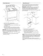
to front of cooktop** F. Model/serial rating plate (located on the left side frame behind storage drawer or right side of frame behind the oven door) IMPORTANT: Range must be level after installation. Follow the instructions in the "Level Range" section. Using the cooktop as a reference for leveling - Whirlpool WFE540H0AH | Installation Guide - Page 5
cover. Cord should be Type SRD or SRDT with a UL listed strain relief and be at least 4 ft (1.22 m) long. ■ Range must be connected to the proper electrical voltage and frequency as specified on the model/serial rating plate. The model/serial rating plate is located on the left side frame behind - Whirlpool WFE540H0AH | Installation Guide - Page 6
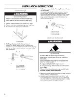
. C A 1. Remove shipping materials, tape and film from range. 2. Remove oven racks and parts package from inside oven. 3. Do not remove the shipping base can tip the range and be killed. Install anti-tip bracket to floor or wall per installation instructions. Slide range back so rear range foot is - Whirlpool WFE540H0AH | Installation Guide - Page 7
to the wall or floor with the two #12 x 1⁵⁄₈" screws provided. 6. Move range close enough to opening to allow for final electrical connections. Remove shipping base, cardboard or hardboard from under range. 7. Move range into its final location, making sure rear leveling leg slides into anti-tip - Whirlpool WFE540H0AH | Installation Guide - Page 8
grounded outlet. Failure to follow these instructions can result in death, fire, or electrical shock. Electrical Shock Hazard Disconnect power before servicing. Use 8 gauge copper or 6 gauge aluminum wire. Electrically ground range. Failure to follow these instructions can result in death, fire, or - Whirlpool WFE540H0AH | Installation Guide - Page 9
following instructions for your type of electrical connection: 4-wire (recommended) 3-wire (if 4-wire is not available) Electrical Connection Options If your home has: And you will be Go to Section: connecting to: 4-wire receptacle (NEMA type 14-50R) A UL listed, 250-volt minimum, 40-amp, range - Whirlpool WFE540H0AH | Installation Guide - Page 10
only if local codes permit connecting range may be connected directly to the fuse disconnect or circuit breaker box. Depending on your electrical electrical connection according to your type of electrical supply (4-wire or 3-wire connection). C D A. Terminal block B. Ground-link screw C. UL listed - Whirlpool WFE540H0AH | Installation Guide - Page 11
■ Recreational vehicles ■ In an area where local codes prohibit grounding through the neutral 1. Part of metal ground strap must be cut out and Use a Phillips screwdriver to remove the ground-link screw from the back of the range. Save the ground-link screw and the end of the ground link under the - Whirlpool WFE540H0AH | Installation Guide - Page 12
codes permit connecting ground conductor to neutral supply wire. 1. Pull the wires through the conduit on cord/conduit plate on bottom of range your countertop is mounted with a backsplash, it may be necessary to grasp the range higher than is shown in the illustration. C D E A. Terminal lug B. - Whirlpool WFE540H0AH | Installation Guide - Page 13
" section of the Use and Care Guide, or the cover or "Warranty" section of the User Instructions, to contact service. Level Range Determine if you have AquaLift™ Technology or Steam Clean by referring to the "Range Care" section of the User Instructions. For Ranges with AquaLift™ Technology or Steam - Whirlpool WFE540H0AH | Installation Guide - Page 14
glides on both sides. Storage Drawer (on some models) The storage drawer can be removed. Before removing, placed in the drawer. Oven Door For normal range use, it is not suggested to remove the sure the oven is off and cool. Then, follow these instructions. The oven door is heavy. To Remove: 1. Open - Whirlpool WFE540H0AH | Installation Guide - Page 15
control displays an "F9" or "F9, E0" error code, the electrical outlet in the home may be miswired. Contact a qualified electrician to verify the electrical supply. ■ See the "Troubleshooting" section in the Use and Care Guide or User Instructions. When the range has been on for 5 minutes, check for - Whirlpool WFE540H0AH | Installation Guide - Page 16
W10403811B © 2011. All rights reserved. TM AQUALIFT is a trademark of Whirlpool, U.S.A. 12/11 Printed in U.S.A.
-
 1
1 -
 2
2 -
 3
3 -
 4
4 -
 5
5 -
 6
6 -
 7
7 -
8
-
9
-
10
-
11
-
12
-
13
-
14
-
15
-
16
 |
 |

INSTALLATION INSTRUCTIONS
30" (76 CM) FREESTANDING ELECTRIC RANGES
Table of Contents
RANGE SAFETY
.............................................................................
2
INSTALLATION REQUIREMENTS
................................................
3
Tools and Parts
............................................................................
3
Location Requirements
................................................................
3
Electrical Requirements - U.S.A. Only
.........................................
5
INSTALLATION INSTRUCTIONS
..................................................
6
Unpack Range
.............................................................................
6
Install Anti-Tip Bracket
.................................................................
6
Electrical Connection - U.S.A. Only
.............................................
8
Verify Anti-Tip Bracket Is Installed and Engaged
......................
12
Level Range
...............................................................................
13
Warming Drawer or Premium Storage Drawer
..........................
13
Storage Drawer
..........................................................................
14
Oven Door
..................................................................................
14
Complete Installation
.................................................................
15
Moving the Range
......................................................................
15
IMPORTANT:
Save for local electrical inspector's use.
W10403811B