Whirlpool WFG114SVB Installation Instructions
Whirlpool WFG114SVB - 30 Inch Gas Range Manual
 |
UPC - 883049147321
View all Whirlpool WFG114SVB manuals
Add to My Manuals
Save this manual to your list of manuals |
Whirlpool WFG114SVB manual content summary:
- Whirlpool WFG114SVB | Installation Instructions - Page 1
-Tip Bracket Location 9 Level Range 9 Electronic Ignition System 10 Complete Installation 11 GAS CONVERSIONS 12 LP Gas Conversion 12 Complete Conversion 14 Natural Gas Conversion 14 Complete Conversion 15 IMPORTANT: Installer: Leave installation instructions with the homeowner. Homeowner - Whirlpool WFG114SVB | Installation Instructions - Page 2
from a neighbor's phone. Follow the gas supplier's instructions. • If you cannot reach your gas supplier, call the fire department. - Installation and service must be performed by a qualified installer, service agency or the gas supplier. WARNING: Gas leaks cannot always be detected by smell - Whirlpool WFG114SVB | Installation Instructions - Page 3
compound resistant to LP gas ■ Noncorrosive leak-detection solution Parts supplied Check that all parts are included. A model/serial rating plate. The model/serial rating plate is located on the oven frame behind the left side of the broiler door. A A. Model/serial rating plate location ■ The range - Whirlpool WFG114SVB | Installation Instructions - Page 4
fronts by ½" (13.0 mm) minimum. IMPORTANT: If installing a range hood or microwave hood combination above the range, follow the range hood or microwave hood combination installation instructions for dimensional clearances above the cooktop surface. B D C A H E G A J I B C F K M L NL - Whirlpool WFG114SVB | Installation Instructions - Page 5
the manufacturer's instructions. Type of Gas Natural gas: This range is design-certified by CSA International for use with Natural gas or, after proper conversion, for use with LP gas. ■ This range is factory set for use with Natural gas. See "Gas Conversions" section. The model/serial rating plate - Whirlpool WFG114SVB | Installation Instructions - Page 6
proper operation: Natural gas: Minimum pressure: 5" WCP Maximum pressure: 14" WCP LP gas: Minimum pressure: 11" WCP Maximum pressure: 14" WCP Contact local gas supplier if you are not sure about the inlet pressure. Burner Input Requirements Input ratings shown on the model/serial rating plate are - Whirlpool WFG114SVB | Installation Instructions - Page 7
foot. Reconnect the anti-tip bracket, if the range is moved. Failure to follow these instructions can result in death or serious burns to children and adults. Contact a qualified floor covering installer for the best procedure for drilling mounting holes through your type of floor covering. Before - Whirlpool WFG114SVB | Installation Instructions - Page 8
tighten, connect the gas supply to the range. B C A D E F G A. Pressure regulator connection fitting B. 90° elbow C. Black iron pipe D. Union E. Nipple F. Manual shutoff valve G. ½" or ¾" gas pipe Typical flexible connection 1. Apply pipe-joint compound made for use with LP gas to the smaller - Whirlpool WFG114SVB | Installation Instructions - Page 9
. Do not use an extension cord. Failure to follow these instructions can result in death, fire, or electrical shock. 7. Plug range back so the rear range foot is under the anti- tip bracket. Front View Front Side View Shutoff valve "ON" Position 3. Open the manual shutoff valve in the gas - Whirlpool WFG114SVB | Installation Instructions - Page 10
Ignition System Initial lighting and gas flame adjustments If the low flame needs adjusting: Cooktop and out, turn the control knob to the "OFF" position. 6. Check each cooktop burner for proper low flame. The low flame should be a minimum, steady blue flame. The flame size should be ¼" to ³⁄₈" - Whirlpool WFG114SVB | Installation Instructions - Page 11
and Care Guide for specific instruction on range operation. If range does not operate, check the following: ■ Household fuse is intact and tight, or circuit breaker has not tripped. ■ Range is plugged into a grounded 3 prong outlet. ■ Electrical supply is connected. ■ See "Troubleshooting" in the - Whirlpool WFG114SVB | Installation Instructions - Page 12
to do so can result in death, explosion, or fire. Gas conversions from Natural gas to LP gas or from LP gas to Natural gas must be done by a qualified installer. LP Gas Conversion WARNING A A. Gas pressure regulator IMPORTANT: Do not remove the gas pressure regulator. NOTE: Do not remove the spring - Whirlpool WFG114SVB | Installation Instructions - Page 13
literature bag included with the range. Three LP gas spuds are stamped "88" and one "96." 3. Remove Natural gas orifice spuds using a 7 mm combination wrench. 4. Install LP gas orifice spuds using a 7 mm combination wrench. 5. Place the Natural gas orifice spuds in the parts bag for future use and - Whirlpool WFG114SVB | Installation Instructions - Page 14
cone is not as distinct as the inner cone. LP gas flames have a slightly yellow tip. 4. Close the broiler door and turn the knob to "OFF." 5. Refer to the "Complete Installation" section to complete this procedure. Natural Gas Conversion WARNING 3. Open broiler door and remove broiler pan. The - Whirlpool WFG114SVB | Installation Instructions - Page 15
bag included with the range. Three natural gas spuds are stamped "149" and one "165." 3. Remove the LP gas orifice spuds using a 7 mm combination wrench. 4. Install the Natural gas orifice spuds using a 7 mm combination wrench. 5. Place LP gas orifice spuds in the parts bag for future use - Whirlpool WFG114SVB | Installation Instructions - Page 16
W10032050B © 2009. All rights reserved. 9/09 Printed in Mexico
-
 1
1 -
 2
2 -
 3
3 -
 4
4 -
 5
5 -
 6
6 -
 7
7 -
8
-
9
-
10
-
11
-
12
-
13
-
14
-
15
-
16
 |
 |

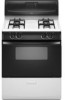
INSTALLATION INSTRUCTIONS
30" (76.2 CM) FREESTANDING GAS RANGES
with standard clean oven
Table of Contents
RANGE SAFETY
.............................................................................
2
INSTALLATION REQUIREMENTS
................................................
3
Tools and Parts
............................................................................
3
Location Requirements
................................................................
3
Electrical Requirements
...............................................................
5
Gas Supply Requirements
...........................................................
5
INSTALLATION INSTRUCTIONS
..................................................
7
Unpack Range
.............................................................................
7
Install Anti-Tip Bracket
................................................................
7
Make Gas Connection
.................................................................
8
Verify Anti-Tip Bracket Location
..................................................
9
Level Range
.................................................................................
9
Electronic Ignition System
.........................................................
10
Complete Installation
.................................................................
11
GAS CONVERSIONS
...................................................................
12
LP Gas Conversion
....................................................................
12
Complete Conversion
................................................................
14
Natural Gas Conversion
.............................................................
14
Complete Conversion
................................................................
15
IMPORTANT:
Installer:
Leave installation instructions with the homeowner.
Homeowner:
Keep installation instructions for future reference.
W10032050B