Whirlpool WFG114SWQ Installation Instructions
Whirlpool WFG114SWQ Manual
 |
UPC - 883049221847
View all Whirlpool WFG114SWQ manuals
Add to My Manuals
Save this manual to your list of manuals |
Whirlpool WFG114SWQ manual content summary:
- Whirlpool WFG114SWQ | Installation Instructions - Page 1
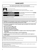
INSTALLATION INSTRUCTIONS 30" (76.2 CM) FREESTANDING GAS RANGES with standard clean oven Table of Contents RANGE SAFETY 2 INSTALLATION REQUIREMENTS 3 Tools and Parts 3 Location Requirements 3 Electrical Requirements 5 Gas Supply Requirements 5 INSTALLATION INSTRUCTIONS 7 Unpack Range 7 - Whirlpool WFG114SWQ | Installation Instructions - Page 2
to light any appliance. • Do not touch any electrical switch. • Do not use any phone in your building. • Immediately call your gas supplier from a neighbor's phone. Follow the gas supplier's instructions. • If you cannot reach your gas supplier, call the fire department. - Installation and service - Whirlpool WFG114SWQ | Installation Instructions - Page 3
-tip bracket to rear range foot. Reconnect the anti-tip bracket, if the range is moved. Failure to follow these instructions can result in death or serious burns to children and adults. INSTALLATION REQUIREMENTS Tools and Parts Gather the required tools and parts before starting installation. Read - Whirlpool WFG114SWQ | Installation Instructions - Page 4
is greater than 24" (61.0 cm), oven frame must extend beyond cabinet fronts by ½" (13.0 mm) minimum. IMPORTANT: If installing a range hood or microwave hood combination above the range, follow the range hood or microwave hood combination installation instructions for dimensional clearances above the - Whirlpool WFG114SWQ | Installation Instructions - Page 5
the manufacturer's instructions. Type of Gas Natural gas: This range is design-certified by CSA International for use with Natural gas or, after proper conversion, for use with LP gas. ■ This range is factory set for use with Natural gas. See "Gas Conversions" section. The model/serial rating plate - Whirlpool WFG114SWQ | Installation Instructions - Page 6
of ½ psi (3.5 kPa). Line pressure testing at ½ psi gauge (14" WCP) or lower The range must be isolated from the gas supply piping system by closing its individual manual shutoff valve during any pressure testing of the gas supply piping system at test pressures equal to or less than ½ psi (3.5 kPa - Whirlpool WFG114SWQ | Installation Instructions - Page 7
under range. 3. Remove oven racks and parts package from inside oven. 4. To place range on its back, take 4 cardboard corners from the carton. Stack one cardboard corner on top of another. Repeat with the other 2 corners. Place them lengthwise on the floor behind the range to support the range when - Whirlpool WFG114SWQ | Installation Instructions - Page 8
tighten, connect the gas supply to the range. B C A D E F G A. Pressure regulator connection fitting B. 90° elbow C. Black iron pipe D. Union E. Nipple F. Manual shutoff valve G. ½" or ¾" gas pipe Typical flexible connection 1. Apply pipe-joint compound made for use with LP gas to the smaller - Whirlpool WFG114SWQ | Installation Instructions - Page 9
when the handle is parallel to the gas pipe. A B A. Closed valve B. Open valve 4. Test all connections by brushing on an approved noncorrosive leak-detection solution. Bubbles will show a leak. Correct any leak found. Level Range 1. Place rack in oven. 2. Place level on rack and check levelness - Whirlpool WFG114SWQ | Installation Instructions - Page 10
. 2. Press the START/ENTER pad. ■ The "TEMP" and "ON" indicators will light. ■ The oven burner should light in 20-40 seconds; this delay is normal. The oven valve requires a certain time before it will open and allow gas to flow. To avoid damaging the hot surface igniter, do not insert any object - Whirlpool WFG114SWQ | Installation Instructions - Page 11
and Care Guide for specific instruction on range operation. If range does not operate, check the following: ■ Household fuse is intact and tight, or circuit breaker has not tripped. ■ Range is plugged into a grounded 3 prong outlet. ■ Electrical supply is connected. ■ See "Troubleshooting" in the - Whirlpool WFG114SWQ | Installation Instructions - Page 12
and authorized service personnel. Failure to do so can result in death, explosion, or fire. Gas conversions from Natural gas to LP gas or from LP gas to Natural gas must be done by a qualified installer. LP Gas Conversion WARNING A A. Gas pressure regulator IMPORTANT: Do not remove the gas pressure - Whirlpool WFG114SWQ | Installation Instructions - Page 13
spreader and set aside. 2. Lift oven burner. The orifice spud is behind the oven burner air shutter. 3. Locate LP gas orifice spud stamped "56" in the bag containing literature supplied with the range. A B A. Spud B. Holder NOTE: Depending on model, the range cooktop may be equipped with 4 standard - Whirlpool WFG114SWQ | Installation Instructions - Page 14
foot. Reconnect the anti-tip bracket, if the range is moved. Failure to follow these instructions can result in death or serious burns to children and adults. A A. Cap To Convert Gas Pressure Regulator 6. Reinstall the cap. 1. Turn manual shutoff valve to the "closed" position. B A C A. To - Whirlpool WFG114SWQ | Installation Instructions - Page 15
parts bag along with LP gas cooktop burner spuds for future use and keep with the bag containing literature. 7. Reinstall oven burner. 8. Reinstall oven racks, oven tray and flame spreader. Complete Conversion 1. Refer to the "Make Gas Connection" section for properly connecting the range to the gas - Whirlpool WFG114SWQ | Installation Instructions - Page 16
W10032050B © 2009. All rights reserved. 9/09 Printed in Mexico
-
 1
1 -
 2
2 -
 3
3 -
 4
4 -
 5
5 -
 6
6 -
 7
7 -
8
-
9
-
10
-
11
-
12
-
13
-
14
-
15
-
16
 |
 |

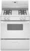
INSTALLATION INSTRUCTIONS
30" (76.2 CM) FREESTANDING GAS RANGES
with standard clean oven
Table of Contents
RANGE SAFETY
.............................................................................
2
INSTALLATION REQUIREMENTS
................................................
3
Tools and Parts
............................................................................
3
Location Requirements
................................................................
3
Electrical Requirements
...............................................................
5
Gas Supply Requirements
...........................................................
5
INSTALLATION INSTRUCTIONS
..................................................
7
Unpack Range
.............................................................................
7
Install Anti-Tip Bracket
................................................................
7
Make Gas Connection
.................................................................
8
Verify Anti-Tip Bracket Location
..................................................
9
Level Range
.................................................................................
9
Electronic Ignition System
.........................................................
10
Complete Installation
.................................................................
11
GAS CONVERSIONS
...................................................................
12
LP Gas Conversion
....................................................................
12
Complete Conversion
................................................................
14
Natural Gas Conversion
.............................................................
14
Complete Conversion
................................................................
15
IMPORTANT:
Installer:
Leave installation instructions with the homeowner.
Homeowner:
Keep installation instructions for future reference.
W10032050B