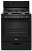
Whirlpool WFG320M0B Installation Instructions
Whirlpool WFG320M0B Manual
 |
View all Whirlpool WFG320M0B manuals
Add to My Manuals
Save this manual to your list of manuals |
Whirlpool WFG320M0B manual content summary:
- Whirlpool WFG320M0B | Installation Instructions - Page 1
of Contents RANGE SAFETY 2 INSTALLATION REQUIREMENTS 3 Tools and Parts 3 Location Requirements 4 Electrical Requirements 5 Gas Supply Requirements 6 INSTALLATION INSTRUCTIONS 7 Unpack Range 7 Install Anti-Tip Bracket 7 Make Gas Connection 8 Verify Anti-Tip Bracket Is Installed and Engaged - Whirlpool WFG320M0B | Installation Instructions - Page 2
tell you what can happen if the instructions are not followed. WARNING: If the information in this manual is not followed exactly, a fire or instructions. • If you cannot reach your gas supplier, call the fire department. - Installation and service must be performed by a qualified installer, service - Whirlpool WFG320M0B | Installation Instructions - Page 3
be killed. Install anti-tip bracket to floor or wall per installation instructions. Slide range back so rear range foot is engaged in the slot range without anti-tip bracket installed and engaged. Failure to follow these instructions can result in death or serious burns to children and adults. Anti - Whirlpool WFG320M0B | Installation Instructions - Page 4
Location Requirements IMPORTANT: Observe all governing codes and ordinances. Do not obstruct flow of combustion and ventilation air. ■ It is the installer's responsibility to comply with installation clearances specified on the model/serial rating plate. The model/serial rating plate is located on - Whirlpool WFG320M0B | Installation Instructions - Page 5
a grounded 3 prong outlet. Do not remove ground prong. Do not use an adapter. Do not use an extension cord. Failure to follow these instructions can result in death, fire, or electrical shock. IMPORTANT: The range must be electrically grounded in accordance with local codes and ordinances, or in - Whirlpool WFG320M0B | Installation Instructions - Page 6
range must be conducted according to the manufacturer's instructions. See "Complete Connection" in the "Make Gas : The supply line must be equipped with a manual shutoff valve. This valve should be located in the : Conversion must be done by a qualified service technician. No attempt shall be made to - Whirlpool WFG320M0B | Installation Instructions - Page 7
supply piping system by closing its individual manual shutoff valve during any pressure testing of the gas psi (3.5 kPa/14" WCP). INSTALLATION INSTRUCTIONS Unpack Range WARNING Excessive Weight Hazard Use bottom firmly to remove, then remove foam support. 7. Use an adjustable wrench to loosen the - Whirlpool WFG320M0B | Installation Instructions - Page 8
include: licensed heating personnel, authorized gas company personnel, and authorized service personnel. Failure to do so can result in death, explosion, or hardboard to continue installing the range using the following installation instructions. A B D C E F G H A. Pressure regulator - Whirlpool WFG320M0B | Installation Instructions - Page 9
work, verify that the valve is in the "ON" position. 3. Open the manual shutoff valve in the gas supply line. The valve is open when the handle is use an adapter. Do not use an extension cord. Failure to follow these instructions can result in death, fire, or electrical shock. 6. Plug into a grounded - Whirlpool WFG320M0B | Installation Instructions - Page 10
the range without anti-tip bracket installed and engaged. Please reference the "Assistance or Service" section of the Use and Care Guide, or the cover or "Warranty" section of the User Instructions, to contact service. Level Range 1. Place a standard flat rack in oven. 2. Place level on the rack and - Whirlpool WFG320M0B | Installation Instructions - Page 11
If the low flame needs adjusting: 1. Turn control knob to the "LOW" setting and remove control knob. 2. Insert a small flat-blade screwdriver into the valve stem. Turn the valve adjusting screw to obtain the smallest flame that will not go out when the control of a cold burner is quickly turned from - Whirlpool WFG320M0B | Installation Instructions - Page 12
■ See "Troubleshooting" in the Use and Care Guide or User Instructions. 8. When personnel, and authorized service personnel. Failure to instructions can result in death or serious burns to children and adults. 1. Turn manual shutoff valve to the "closed" position. B A C A. Gas supply line B. Manual - Whirlpool WFG320M0B | Installation Instructions - Page 13
To Convert Gas Pressure Regulator 1. Open broiler door and remove broiler rack. The gas pressure regulator is located in the back right hand corner of the broiler compartment. A To Convert Surface Burners 1. Remove burner grate, burner caps and burners. A. Gas pressure regulator IMPORTANT: Do not - Whirlpool WFG320M0B | Installation Instructions - Page 14
without anti-tip bracket installed and engaged. Failure to follow these instructions can result in death or serious burns to children and adults. 1. Turn manual shutoff valve to the "closed" position. B A C A. Gas supply line B. Manual shutoff valve "closed" position C. To range 2. Unplug range or - Whirlpool WFG320M0B | Installation Instructions - Page 15
To Convert Gas Pressure Regulator 1. Open broiler door and remove broiler rack. The gas pressure regulator is located in the back right hand corner of the broiler compartment. A To Convert Surface Burners 1. Remove burner grate, burner caps and burners. A. Gas pressure regulator IMPORTANT: Do not - Whirlpool WFG320M0B | Installation Instructions - Page 16
and flame spreader. Complete Conversion 1. Refer to the "Make Gas Connection" section for properly connecting the range to the gas supply. 2. Turn the manual shutoff valve in the gas supply line to the open position. 3. Refer to the "Electronic Ignition System" section for proper burner ingestion
-
 1
1 -
 2
2 -
 3
3 -
 4
4 -
 5
5 -
 6
6 -
 7
7 -
8
-
9
-
10
-
11
-
12
-
13
-
14
-
15
-
16
 |
 |

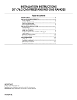
INSTALLATION INSTRUCTIONS
30" (76.2 CM) FREESTANDING GAS RANGES
Table of Contents
RANGE SAFETY
...................................................................................
2
INSTALLATION REQUIREMENTS
.....................................................
3
Tools and Parts
..................................................................................
3
Location Requirements
.....................................................................
4
Electrical Requirements
.....................................................................
5
Gas Supply Requirements
................................................................
6
INSTALLATION INSTRUCTIONS
.......................................................
7
Unpack Range
...................................................................................
7
Install Anti-Tip Bracket
......................................................................
7
Make Gas Connection
.......................................................................
8
Verify Anti-Tip Bracket Is Installed and Engaged
.............................
9
Level Range
.....................................................................................
10
Electronic Ignition System
...............................................................
10
Complete Installation
.......................................................................
12
GAS CONVERSIONS
.........................................................................
12
LP Gas Conversion
..........................................................................
12
Complete Conversion
......................................................................
14
Natural Gas Conversion
..................................................................
14
Complete Conversion
......................................................................
16
W10620413E
IMPORTANT:
Save for local inspector's use.
Installer:
Leave installation instructions with the homeowner.
Homeowner:
Keep installation instructions for future reference.