Whirlpool WFG320M0BB Installation Guide
Whirlpool WFG320M0BB Manual
 |
View all Whirlpool WFG320M0BB manuals
Add to My Manuals
Save this manual to your list of manuals |
Whirlpool WFG320M0BB manual content summary:
- Whirlpool WFG320M0BB | Installation Guide - Page 1
3 Tools and Parts 3 Location Requirements 4 Electrical Requirements 5 Gas Supply Requirements 6 INSTALLATION INSTRUCTIONS 7 Unpack Range 7 Install Anti-Tip Bracket 7 Make Gas Connection 8 Verify Anti-Tip Bracket Is Installed and Engaged 9 Level Range 10 Electronic Ignition System 10 - Whirlpool WFG320M0BB | Installation Guide - Page 2
follow the "What to do if you smell gas" instructions. IMPORTANT: Do not install a ventilation system that blows air downward toward this gas cooking appliance. This type of ventilation system may cause ignition and combustion problems with this gas cooking appliance resulting in personal injury or - Whirlpool WFG320M0BB | Installation Guide - Page 3
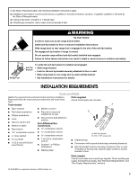
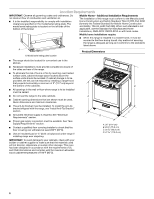
or wall. • Slide range back so rear range foot is under anti-tip bracket. • See installation instructions for details. INSTALLATION REQUIREMENTS Tools and Parts Gather the required tools and parts before starting installation. Parts supplied Read and follow the instructions provided with any - Whirlpool WFG320M0BB | Installation Guide - Page 4
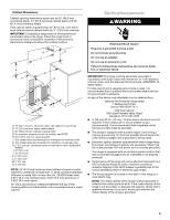
rating plate. The model/serial rating plate is located on the left side of the bottom of the broiler. Mobile Home - Additional Installation Requirements The installation of this range must conform to the Manufactured Home Construction and Safety Standard, Title 24 CFR, Part 3280 (formerly the - Whirlpool WFG320M0BB | Installation Guide - Page 5
: If installing a range hood or microwave hood combination above the range, follow the range hood or microwave hood combination installation instructions for dimensional power and is correctly grounded. This range is equipped with an electronic ignition system that will not operate if plugged - Whirlpool WFG320M0BB | Installation Guide - Page 6
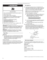
absence of local codes, installation must conform with American National Standard, National Fuel Gas Code ANSI Z223.1 - latest edition or CAN/CGA B149 - latest edition. IMPORTANT: Leak testing of the range must be conducted according to the manufacturer's instructions. See "Complete Connection" in - Whirlpool WFG320M0BB | Installation Guide - Page 7
must be isolated from the gas supply piping system by closing its individual manual shutoff valve during any pressure testing of the gas supply piping system at test pressures equal to or less than ½ psi (3.5 kPa/14" WCP). INSTALLATION INSTRUCTIONS Unpack Range WARNING Excessive Weight Hazard Use - Whirlpool WFG320M0BB | Installation Guide - Page 8
to continue installing the range using the following installation instructions. A B D C E F G H A. Pressure regulator connection fitting B. Use pipe-joint compound. C. Adapter D. Flexible connector E. Adapter F. Use pipe-joint compound. G. Manual shutoff valve H. ½" or ¾" gas pipe 8 - Whirlpool WFG320M0BB | Installation Guide - Page 9
"ON" position. If the range does not work, verify that the valve is in the "ON" position. 3. Open the manual shutoff valve in the gas supply line. The valve is open when the handle is parallel to the gas pipe. A B 5. Remove cooktop burner caps and grates from parts package. Align notches in burner - Whirlpool WFG320M0BB | Installation Guide - Page 10
" section of the User Instructions, to contact service. Level Range 1. Place a standard flat rack in oven. 2. Place level on the rack and check levelness of the range, first side to side; then front to back. Low Med Electronic Ignition System Initial lighting and gas flame adjustments Cooktop and - Whirlpool WFG320M0BB | Installation Guide - Page 11
from "HIGH" to "LOW." Turn right to decrease flame height of Oven/Broil Burner Electronic oven control (on some models): 1. Open broiler door. 2. Press the " gas to flow. To avoid damaging the hot surface igniter, do not insert any object into the openings of the shield that surrounds the igniter - Whirlpool WFG320M0BB | Installation Guide - Page 12
or Service" section of the Use and Care Guide or the cover of the User Instructions, or contact the dealer from whom you purchased your range. GAS CONVERSIONS Gas conversions from Natural gas to LP gas or from LP gas to Natural gas must be done by a qualified installer. LP Gas Conversion - Whirlpool WFG320M0BB | Installation Guide - Page 13
containing literature included with the range. One LP gas spud is stamped "88 (Yellow/Black)," two are stamped "116 (Yellow/Orange)," and one is stamped "70 (Yellow/White)." 3. Remove Natural gas orifice spuds using a 7 mm combination wrench. 4. Install LP gas orifice spuds using a 7 mm combination - Whirlpool WFG320M0BB | Installation Guide - Page 14
bracket if range is moved. Do not operate range without anti-tip bracket installed and engaged. Failure to follow these instructions can result in death or serious burns to children and adults. 1. Turn manual shutoff valve to the "closed" position. B A C A. Gas supply line B. Manual shutoff valve - Whirlpool WFG320M0BB | Installation Guide - Page 15
bag containing literature included with the range. Two Natural gas spuds are stamped "194 (Black/White)," one is stamped "155 (Red/Brown)," and one is stamped "110 (Red/Brass)." 3. Remove the LP gas orifice spuds using a 7 mm combination wrench. 4. Install the Natural gas orifice spuds using a 7 mm - Whirlpool WFG320M0BB | Installation Guide - Page 16
connecting the range to the gas supply. 2. Turn the manual shutoff valve in the gas supply line to the open position. 3. Refer to the "Electronic Ignition System" section for proper burner ingestion, operation and burner flame adjustments. IMPORTANT: You may have to adjust the "LOW" setting for
-
 1
1 -
 2
2 -
 3
3 -
 4
4 -
 5
5 -
 6
6 -
 7
7 -
8
-
9
-
10
-
11
-
12
-
13
-
14
-
15
-
16
 |
 |

INSTALLATION INSTRUCTIONS
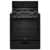
30" (76.2 CM) FREESTANDING GAS RANGES
Table of Contents
RANGE SAFETY
...................................................................................
2
INSTALLATION REQUIREMENTS
.....................................................
3
Tools and Parts
..................................................................................
3
Location Requirements
.....................................................................
4
Electrical Requirements
.....................................................................
5
Gas Supply Requirements
................................................................
6
INSTALLATION INSTRUCTIONS
.......................................................
7
Unpack Range
...................................................................................
7
Install Anti-Tip Bracket
......................................................................
7
Make Gas Connection
.......................................................................
8
Verify Anti-Tip Bracket Is Installed and Engaged
.............................
9
Level Range
.....................................................................................
10
Electronic Ignition System
...............................................................
10
Complete Installation
.......................................................................
12
GAS CONVERSIONS
.........................................................................
12
LP Gas Conversion
..........................................................................
12
Complete Conversion
......................................................................
14
Natural Gas Conversion
..................................................................
14
Complete Conversion
......................................................................
16
W10620413E
IMPORTANT:
Save for local inspector's use.
Installer:
Leave installation instructions with the homeowner.
Homeowner:
Keep installation instructions for future reference.