Whirlpool WFG361LVQ Installation Guide
Whirlpool WFG361LVQ - 30 Inch Gas Range Manual
 |
UPC - 883049139135
View all Whirlpool WFG361LVQ manuals
Add to My Manuals
Save this manual to your list of manuals |
Whirlpool WFG361LVQ manual content summary:
- Whirlpool WFG361LVQ | Installation Guide - Page 1
INSTRUCTIONS 30" (76.2 CM) FREESTANDING GAS RANGES Table of Contents RANGE SAFETY 1 INSTALLATION REQUIREMENTS 3 Tools and Parts 3 Location Requirements 3 Electrical Requirements 5 Gas Supply Requirements 5 INSTALLATION INSTRUCTIONS 6 Unpack Range 6 Install Anti-Tip Bracket 7 Make Gas - Whirlpool WFG361LVQ | Installation Guide - Page 2
to light any appliance. • Do not touch any electrical switch. • Do not use any phone in your building. • Immediately call your gas supplier from a neighbor's phone. Follow the gas supplier's instructions. • If you cannot reach your gas supplier, call the fire department. - Installation and service - Whirlpool WFG361LVQ | Installation Guide - Page 3
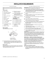
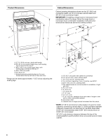
■ It is the installer's responsibility to comply with installation clearances specified on the model/serial rating plate. The model/serial rating plate is located on the oven frame behind the top left side of the oven door. ■ The range should be located for convenient use in the kitchen. ■ Recessed - Whirlpool WFG361LVQ | Installation Guide - Page 4
range hood or microwave hood combination above the range, follow the range hood or microwave hood combination installation instructions Model/serial rating plate (located on the oven frame behind the top left side of the oven door) *Range recommended for installation of rigid gas pipe. G. 4¹⁄₂" (11.4 - Whirlpool WFG361LVQ | Installation Guide - Page 5
the manufacturer's instructions. Type of Gas Natural gas: This range is design-certified by CSA International for use with Natural gas or, after proper conversion, for use with LP gas. ■ This range is factory set for use with Natural gas. See "Gas Conversions" section. The model/serial rating plate - Whirlpool WFG361LVQ | Installation Guide - Page 6
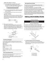
) or lower The range must be isolated from the gas supply piping system by closing its individual manual shutoff valve during any pressure testing of the gas supply piping system at test pressures equal to or less than ½ psi (3.5 kPa). INSTALLATION INSTRUCTIONS Unpack Range WARNING Excessive Weight - Whirlpool WFG361LVQ | Installation Guide - Page 7
foot. Reconnect the anti-tip bracket, if the range is moved. Failure to follow these instructions can result in death or serious burns to children and adults. Contact a qualified floor covering installer for the best procedure for drilling mounting holes through your type of floor covering. Before - Whirlpool WFG361LVQ | Installation Guide - Page 8
found. 4. Remove cooktop burner caps and grates from parts package. Burner caps should be level when properly positioned. If burner caps are not properly positioned, surface burners will not light. Place burner grates over burners and caps. B A C A. Burner base B. Burner cap C. Burner grate 8 - Whirlpool WFG361LVQ | Installation Guide - Page 9
properly positioned on burner bases. Repeat start-up. If a burner does not light at this point, turn the control knobs to "Off" and contact your dealer or authorized service company for assistance. Adjust Flame Height Adjust the height of top burner flames. The cooktop "low" burner flame should be - Whirlpool WFG361LVQ | Installation Guide - Page 10
burner up to 50 to 60 seconds to light. Electronic igniters are used to light the bake and broil burners. Refer to the Use and Care Guide for proper operation of the oven controls. Adjust Oven Bake Burner Flame (if needed) 1. On models center rear of the range. Loosen the locking screw and rotate - Whirlpool WFG361LVQ | Installation Guide - Page 11
burner should light within 8 seconds. Under certain conditions it may take the burner up to 50 to 60 seconds to light. Refer to the Use and Care Guide for proper operation of the oven controls. Adjust Oven Broil Burner some models) Remove all items from inside the warming drawer, and allow the range - Whirlpool WFG361LVQ | Installation Guide - Page 12
the gas supply line shutoff valve is open, press the CANCEL button on the oven control panel and contact a qualified technician. If you need Assistance or Service: Please reference the "Assistance or Service" section of the Use and Care Guide or contact the dealer from whom you purchased your range. - Whirlpool WFG361LVQ | Installation Guide - Page 13
is moved. Failure to follow these instructions can result in death or serious burns to children and adults. 1. Turn the manual shutoff valve to the closed position. B A C A. To range B. Manual shutoff valve "closed" position C. Gas supply line 2. Unplug range or disconnect power. C Side view after - Whirlpool WFG361LVQ | Installation Guide - Page 14
the back of the range near the gas inlet. Gas orifice spuds are stamped with a number, marked with 1 color dot, and have a groove in the hex area. Replace the Natural gas orifice spud with the correct LP gas orifice spud. LP Gas Orifice Spud Chart for Surface Burners Burner Rating Color Size ID - Whirlpool WFG361LVQ | Installation Guide - Page 15
53" hood with a "090" hood. Install the LP gas broiler burner orifice hood, turning it clockwise until snug. IMPORTANT: Do not panel into the oven. 14. Reattach the oven bottom panel with 2 screws. A. Orifice hood 5. Place the broil burner on the broil burner orifice hood and insert the broil burner - Whirlpool WFG361LVQ | Installation Guide - Page 16
is moved. Failure to follow these instructions can result in death or serious burns to children and adults. 1. Turn the manual shutoff valve to the closed position. B A C A. To range B. Manual shutoff valve "closed" position C. Gas supply line 2. Unplug range or disconnect power. B D E NG NG - Whirlpool WFG361LVQ | Installation Guide - Page 17
Natural gas orifice spud placement. Natural Gas Orifice Spud Chart Burner Rating Color Size Model Number and Serial Number Plate located on the oven frame behind the top left side of the oven door for proper sizing of spuds for each burner location. 5. Place LP gas orifice spuds in plastic parts - Whirlpool WFG361LVQ | Installation Guide - Page 18
hood with a "53" hood. Install the Natural gas broiler burner orifice hood, turning it clockwise until snug. IMPORTANT: Instructions" section of this manual to complete this procedure. B A C A. Broil burner B. Screws C. Orifice hood 3. Use a ³⁄₈" combination wrench and turn the LP gas broil burner - Whirlpool WFG361LVQ | Installation Guide - Page 19
Left edge ANTI-TIP BRACKET TEMPLATE Cut on dotted lines and place the left edge against the left side cabinet and the top edge against the rear wall. Top edge 19 - Whirlpool WFG361LVQ | Installation Guide - Page 20
W10413012A © 2011. All rights reserved. 5/11 Printed in U.S.A.
-
 1
1 -
 2
2 -
 3
3 -
 4
4 -
 5
5 -
 6
6 -
 7
7 -
8
-
9
-
10
-
11
-
12
-
13
-
14
-
15
-
16
-
17
-
18
-
19
-
20
 |
 |
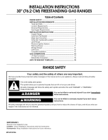
INSTALLATION INSTRUCTIONS
30" (76.2 CM) FREESTANDING GAS RANGES
RANGE SAFETY
Table of Contents
RANGE SAFETY
.............................................................................
1
INSTALLATION REQUIREMENTS
...............................................
3
Tools and Parts
............................................................................
3
Location Requirements
...............................................................
3
Electrical Requirements
...............................................................
5
Gas Supply Requirements
..........................................................
5
INSTALLATION INSTRUCTIONS
.................................................
6
Unpack Range
.............................................................................
6
Install Anti-Tip Bracket
................................................................
7
Make Gas Connection
.................................................................
8
Verify Anti-Tip Bracket Location
.................................................
9
Level Range
.................................................................................
9
Electronic Ignition System
...........................................................
9
Warming Drawer
........................................................................
11
Storage Drawer
..........................................................................
11
Oven Door
..................................................................................
12
Complete Installation
.................................................................
12
GAS CONVERSIONS
...................................................................
13
LP Gas Conversion
....................................................................
13
Natural Gas Conversion
............................................................
16
ANTI-TIP BRACKET TEMPLATE
................................................
19
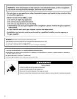
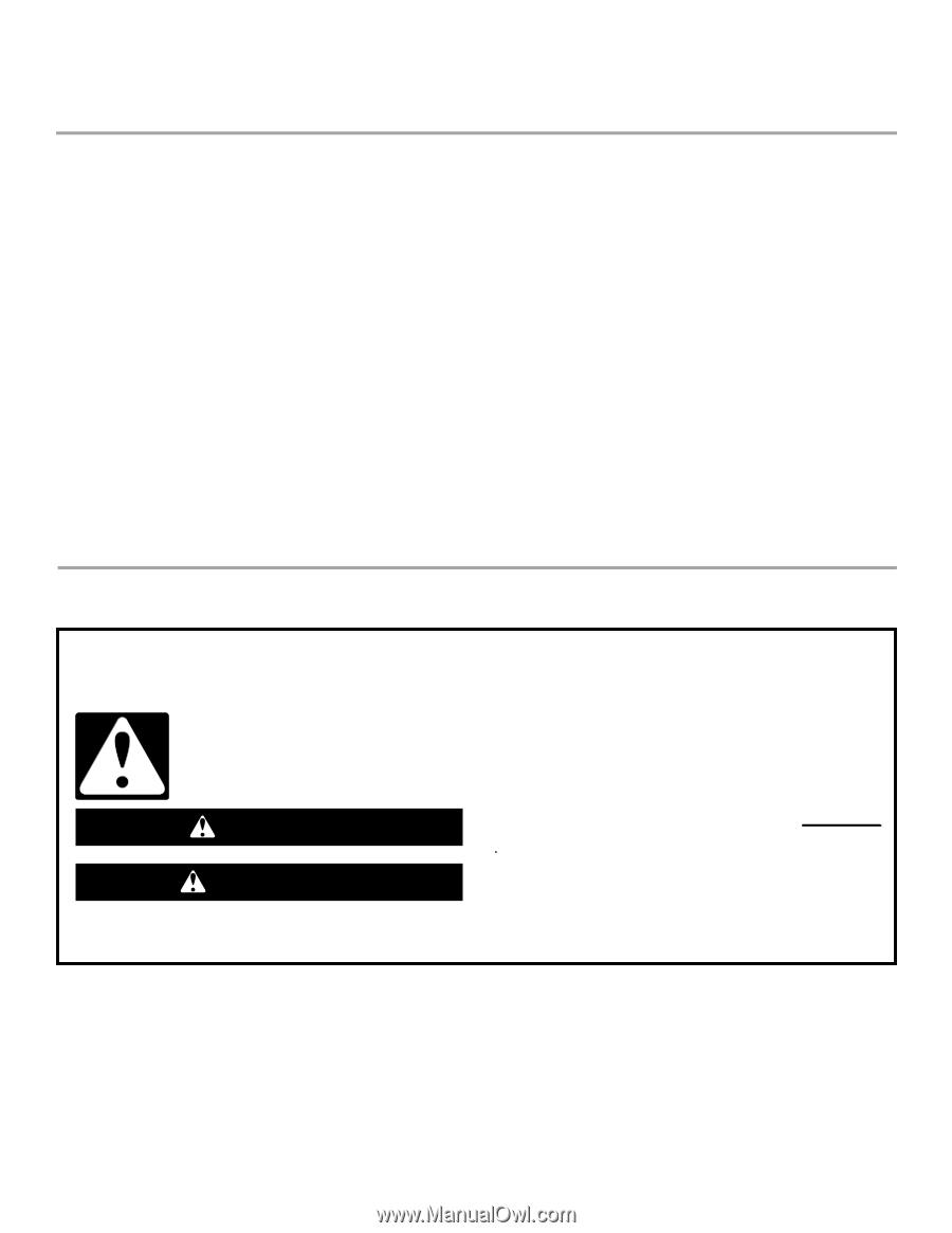
You can be killed or seriously injured if you don't immediately
You
can be killed or seriously injured if you don't follow
All safety messages will tell you what the potential hazard is, tell you how to reduce the chance of injury, and tell you what can
happen if the instructions are not followed.
Your safety and the safety of others are very important.
We have provided many important safety messages in this manual and on your appliance. Always read and obey all safety
messages.
This is the safety alert symbol.
This symbol alerts you to potential hazards that can kill or hurt you and others.
All safety messages will follow the safety alert symbol and either the word “DANGER” or “WARNING.”
These words mean:
follow instructions.
instructions.
DANGER
WARNING
IMPORTANT:
Save for local inspector's use.
Installer:
Leave installation instructions with the homeowner.
Homeowner:
Keep installation instructions for future reference.
W10413012A