Whirlpool WFG361LVS Installation Instructions
Whirlpool WFG361LVS - 5.0 Cubic Foot Gas Range Manual
 |
UPC - 883049139159
View all Whirlpool WFG361LVS manuals
Add to My Manuals
Save this manual to your list of manuals |
Whirlpool WFG361LVS manual content summary:
- Whirlpool WFG361LVS | Installation Instructions - Page 1
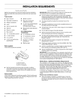
INSTALLATION INSTRUCTIONS 30" (76.2 CM) FREESTANDING GAS RANGES Table of Contents RANGE SAFETY...2 INSTALLATION REQUIREMENTS 4 Tools and Parts...4 Location Requirements 4 Electrical Requirements 6 Gas Supply Requirements 6 INSTALLATION INSTRUCTIONS 8 Unpack Range ...8 Install Anti-Tip Bracket - Whirlpool WFG361LVS | Installation Instructions - Page 2
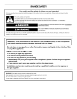
. Follow the gas supplier's instructions. • If you cannot reach your gas supplier, call the fire department. - Installation and service must be performed by a qualified installer, service agency or the gas supplier. WARNING: Gas leaks cannot always be detected by smell. Gas suppliers recommend that - Whirlpool WFG361LVS | Installation Instructions - Page 3
, the following installation instructions apply: ■ Installations and repairs must be performed by a qualified or licensed contractor, plumber, or gasfitter qualified or licensed by the State of Massachusetts. ■ If using a ball valve, it shall be a T-handle type. ■ A flexible gas connector, when - Whirlpool WFG361LVS | Installation Instructions - Page 4
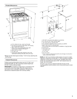
and ventilation air. ■ It is the installer's responsibility to comply with installation clearances specified on the model/serial rating plate. The model/serial rating plate is located on the oven frame behind the top left side of the oven door. ■ The range should be located for convenient use in - Whirlpool WFG361LVS | Installation Instructions - Page 5
or microwave hood combination above the range, follow the range hood or microwave hood combination installation instructions for dimensional clearances above the cooktop surface. A. 18" (45.7 cm) upper side cabinet to countertop B. 13" (33 cm) max. upper cabinet depth C. 30" (76.2 cm) min. opening - Whirlpool WFG361LVS | Installation Instructions - Page 6
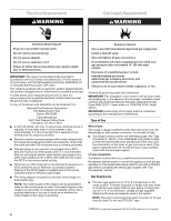
instructions. Type of Gas Natural gas: This range is design-certified by CSA International for use with Natural gas or, after proper conversion, for use with LP gas. ■ This range is factory set for use with Natural gas. See "Gas Conversions" section. The model/serial rating plate located on the oven - Whirlpool WFG361LVS | Installation Instructions - Page 7
must be equipped with a manual shutoff valve. This valve should be located in the same room but external to the range opening, such as an adjacent model/serial rating plate. Line pressure testing above ½ psi gauge (14" WCP) The range and its individual shutoff valve must be disconnected from the gas - Whirlpool WFG361LVS | Installation Instructions - Page 8
INSTALLATION INSTRUCTIONS Unpack Range WARNING Excessive Weight Hazard Use two or more people to move and install range. Failure to do so can result in back or other injury. 1. Remove shipping materials, tape and film from range. 2. Remove oven racks and parts package from inside oven. 3. Do not - Whirlpool WFG361LVS | Installation Instructions - Page 9
in the "Location Requirements" section. 10. Continue installing your range using the following installation instructions. Typical rigid pipe connection A combination of pipe fittings must be used to connect the range to the existing gas line. Your connections may be different, according to - Whirlpool WFG361LVS | Installation Instructions - Page 10
not properly positioned, surface burners will not light. Place burner grates over burners and caps. B A C A. Burner base B. Burner cap C. Burner grate 2. To check that the anti-tip bracket is installed, use a flashlight and look underneath the bottom of the range. ■ Look for the anti-tip bracket - Whirlpool WFG361LVS | Installation Instructions - Page 11
in the anti-tip bracket. NOTE: Range must be level for satisfactory baking performance. Electronic Ignition System Initial lighting and gas flame adjustments Cooktop and oven burners use electronic igniters in place of standing pilots. When the cooktop control knob is turned to the "LITE" position - Whirlpool WFG361LVS | Installation Instructions - Page 12
the burner up to 50 to 60 seconds to light. Electronic igniters are used to light the bake and broil burners. Refer to the Use and Care Guide for proper operation of the oven controls. Adjust Oven Bake Burner Flame (if needed) 1. On models with a warming drawer, remove access cover plate (1 screw - Whirlpool WFG361LVS | Installation Instructions - Page 13
the gas supply line shutoff valve is open, press the CANCEL button on the oven control panel and contact a qualified technician. If you need Assistance or Service: Please reference the "Assistance or Service" section of the Use and Care Guide or contact the dealer from whom you purchased your range - Whirlpool WFG361LVS | Installation Instructions - Page 14
is moved. Failure to follow these instructions can result in death or serious burns to children and adults. 1. Turn the manual shutoff valve to the closed position. B A C A. To range B. Manual shutoff valve "closed" position C. Gas supply line 2. Unplug range or disconnect power. 14 C Side view - Whirlpool WFG361LVS | Installation Instructions - Page 15
for Surface Burners Burner Rating Color Size ID Number 14,000 BTU 11,000 BTU 8,000 BTU 5,000 BTU Yellow/Orange Yellow/Brown Yellow/Black Yellow/White 1.07 mm 0.99 mm 0.85 mm 0.70 mm L107 L99 L85 L70 NOTE: Refer to the Model Number and Serial Number Plate located on the oven frame behind the - Whirlpool WFG361LVS | Installation Instructions - Page 16
yellow tip. 3. Refer to "Complete Installation" in the "Installation Instructions" section of this manual to complete this procedure. Natural Gas Conversion WARNING To Convert Gas Pressure Regulator 1. Remove storage drawer or warming drawer. See "Replace Oven Racks and Warming Drawer" section - Whirlpool WFG361LVS | Installation Instructions - Page 17
correct Natural gas orifice spud placement. Natural Gas Orifice Spud Chart Burner Rating Color Size ID Number 17,000 BTU 15,500 BTU 14,200 BTU 13,000/13,500 BTU 12,000/12,500 BTU 9,500 BTU 8,000 BTU 5,000 BTU Red/Magenta Red/Black Red/Orange Red/Blue Red/Yellow Red/Brown Red/White Red/Brass - Whirlpool WFG361LVS | Installation Instructions - Page 18
conversion is not made. See "Adjust Oven Broil Burner Flame" in the "Electronic Ignition System" section. Complete Installation 1. Refer to the "Make Gas Connection" section for properly connecting the range to the gas supply. 2. Refer to the "Electronic Ignition System" section for proper burner - Whirlpool WFG361LVS | Installation Instructions - Page 19
Left edge ANTI-TIP BRACKET TEMPLATE Cut on dotted lines and place the left edge against the left side cabinet and the top edge against the rear wall. Top edge 19 - Whirlpool WFG361LVS | Installation Instructions - Page 20
W10196161E © 2011. All rights reserved. 1/11 Printed in U.S.A.
-
 1
1 -
 2
2 -
 3
3 -
 4
4 -
 5
5 -
 6
6 -
 7
7 -
8
-
9
-
10
-
11
-
12
-
13
-
14
-
15
-
16
-
17
-
18
-
19
-
20
 |
 |

INSTALLATION INSTRUCTIONS
30" (76.2 CM) FREESTANDING GAS RANGES
Table of Contents
RANGE SAFETY
..........................................................................................................
2
INSTALLATION REQUIREMENTS
.............................................................................
4
Tools and Parts
.........................................................................................................
4
Location Requirements
.............................................................................................
4
Electrical Requirements
............................................................................................
6
Gas Supply Requirements
........................................................................................
6
INSTALLATION INSTRUCTIONS
...............................................................................
8
Unpack Range
..........................................................................................................
8
Install Anti-Tip Bracket
.............................................................................................
8
Make Gas Connection
..............................................................................................
9
Verify Anti-Tip Bracket Location
.............................................................................
10
Level Range
............................................................................................................
11
Electronic Ignition System
......................................................................................
11
Replace Oven Racks and Warming Drawer
...........................................................
12
Storage Drawer
.......................................................................................................
13
Complete Installation
..............................................................................................
13
GAS CONVERSIONS
................................................................................................
14
LP Gas Conversion
.................................................................................................
14
Natural Gas Conversion
..........................................................................................
16
ANTI-TIP BRACKET TEMPLATE
............................................................................
19
IMPORTANT:
Save for local inspector's use.
Installer:
Leave installation instructions with the homeowner.
Homeowner:
Keep installation instructions for future reference.
W10196161E