Whirlpool WFG510S0H Installation Instructions
Whirlpool WFG510S0H Manual
 |
View all Whirlpool WFG510S0H manuals
Add to My Manuals
Save this manual to your list of manuals |
Whirlpool WFG510S0H manual content summary:
- Whirlpool WFG510S0H | Installation Instructions - Page 1
INSTALLATION INSTRUCTIONS 30" (76.2 CM) FREESTANDING GAS RANGES INSTRUCTIONS D'INSTALLATION CUISINIÈRE À GAZ AUTOPORTANTE DE 30" (76,2 CM) Table of Contents/Table des matières RANGE SAFETY 2 INSTALLATION REQUIREMENTS 4 Tools and Parts 4 Location Requirements 4 Electrical Requirements 6 Gas - Whirlpool WFG510S0H | Installation Instructions - Page 2
from a neighbor's phone. Follow the gas supplier's instructions. • If you cannot reach your gas supplier, call the fire department. - Installation and service must be performed by a qualified installer, service agency or the gas supplier. WARNING: Gas leaks cannot always be detected by smell - Whirlpool WFG510S0H | Installation Instructions - Page 3
shall be listed. A flexible gas connector, when used,must not exceed 4 feet (121.9 cm). Range Foot WARNING Tip Over Hazard A child or adult can tip the range and be killed. Install anti-tip bracket to floor or wall per installation instructions. Slide range back so rear range foot is engaged in - Whirlpool WFG510S0H | Installation Instructions - Page 4
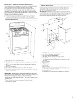
tools and parts before starting installation. Read and follow the instructions provided with any tools listed here. Tools Needed ■■ Tape measure ■■ Flat-blade screwdriver ■■ Phillips screwdriver ■■ Level ■■ Hand or electric drill ■■ Pipe-joint compound resistant to Propane gas ■■ Noncorrosive - Whirlpool WFG510S0H | Installation Instructions - Page 5
24, HUD Part 280). When such standard is not applicable, use the Standard for Manufactured Home Installations, ANSI A225.1/NFPA 501A or with local codes. Mobile home installations require: ■■ When this range is installed in a mobile home, it must be secured according to the instructions in this - Whirlpool WFG510S0H | Installation Instructions - Page 6
CAN/CGA B149 - latest edition. IMPORTANT: Leak testing of the range must be conducted according to the manufacturer's instructions. Type of Gas Natural Gas: ■■ This range is factory set for use with Natural gas. See "Gas Conversions" section. The model/serial rating plate located on the oven frame - Whirlpool WFG510S0H | Installation Instructions - Page 7
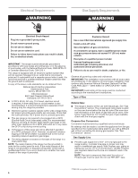
connection. All strains must be removed from the supply and fuel lines so range will be level and in line. ■■ Must include a shutoff valve: Install a manual gas line shut-off valve in an easily accessible location. Do not block access to shut-off valve. The valve is for turning on or shutting - Whirlpool WFG510S0H | Installation Instructions - Page 8
INSTALLATION INSTRUCTIONS Unpack Range Install Anti-Tip Bracket WARNING Excessive Weight Hazard Use two or more people to move and install range. Failure to do so can result in back or other injury. WARNING 1. Remove shipping materials, tape and film from range. 2. Remove oven racks and parts - Whirlpool WFG510S0H | Installation Instructions - Page 9
, authorized gas company personnel, and authorized service personnel. installing the range using the following installation instructions. B C A D F E J I HG A. Gas pressure regulator B. 90° elbow (must have 1/3" [1.2 cm] male pipe thread) C. Nipple D. Union E. Black iron pipe F. Manual gas - Whirlpool WFG510S0H | Installation Instructions - Page 10
manual shutoff valve in the gas supply line. The valve is open when the handle is parallel to the gas pipe. A B WARNING Electrical Shock Hazard Plug into a grounded 3 prong outlet. Do not remove ground prong. Do not use an adapter. Do not use an extension cord. Failure to follow these instructions - Whirlpool WFG510S0H | Installation Instructions - Page 11
installed correctly. Do not operate the range without antitip bracket installed and engaged. Please reference the "Assistance or Service" section of the Use and Care Guide, or the cover or "Warranty" section of the User Instructions, to contact service. Level Range ignites the gas. Check Operation - Whirlpool WFG510S0H | Installation Instructions - Page 12
needs to be adjusted, locate the air shutter near the center rear of the range. Loosen the locking screw and rotate the air shutter until the proper flame to 60 seconds to light. Refer to the Use and Care Guide or User Instructions for proper operation of the oven controls. Adjust Oven Broil Burner - Whirlpool WFG510S0H | Installation Instructions - Page 13
. Warming Drawer or Premium Storage Drawer (on some models) Remove all items from inside the warming drawer or premium storage drawer, and allow the range to cool completely before attempting to remove the drawer. To Remove: 1. Open the warming drawer or premium storage drawer to its fully open - Whirlpool WFG510S0H | Installation Instructions - Page 14
3 prong outlet. ■■ Electrical supply is connected. ■■ See "Troubleshooting" in the Use and Care Guide or User Instructions. 8. When the range has been on for 5 minutes, check for heat. If the range is cold, turn off the range and check that the gas supply line shutoff valve is open. ■■ If the - Whirlpool WFG510S0H | Installation Instructions - Page 15
personnel, authorized gas company personnel, and authorized service personnel. Failure to do so can result in death, explosion, or fire. Tip Over Hazard A child or adult can tip the range and be killed. Install anti-tip bracket to floor or wall per installation instructions. Slide range back so - Whirlpool WFG510S0H | Installation Instructions - Page 16
1 color dot, and have a groove in the hex area. Replace the Natural gas orifice spud with the correct Propane gas orifice spud. LP LP C Side view after A. Plastic cover B. Gas pressure regulator cap with solid end facing out C. Gas pressure regulator cap with hollow end facing out D. Washer - Whirlpool WFG510S0H | Installation Instructions - Page 17
burner orifice hood counterclockwise to remove. The hood will be stamped with a "53." 4. Replace the "53" hood with a "090" hood. Install the Propane gas broiler burner orifice hood, turning it clockwise until snug. IMPORTANT: Do not overtighten. A A x.xx A. Orifice spud 9. Position the back of - Whirlpool WFG510S0H | Installation Instructions - Page 18
3. Refer to "Complete Installation" in the "Installation Instructions" section of this manual to complete this procedure. NOTE: Be sure to save the orifices that have just been replaced in the conversion. Natural Gas Conversion WARNING Tip Over Hazard A child or adult can tip the range and be killed - Whirlpool WFG510S0H | Installation Instructions - Page 19
oven frame behind the top left side of the oven door for proper sizing of spuds for each burner location. 5. Place Propane gas orifice spuds in plastic parts bag for future use and keep with package containing literature. 6. Replace the burner base using both screws. 7. Replace burner cap. 8. Repeat - Whirlpool WFG510S0H | Installation Instructions - Page 20
is very important. Natural gas flames do not have yellow tips. 3. Refer to "Complete Installation" in the "Installation Instructions" section of this manual to complete this procedure. NOTE: Be sure to save the orifices that have just been replaced in the conversion. C A. Broil burner B. Screws - Whirlpool WFG510S0H | Installation Instructions - Page 21
SÉCURITÉ DE LA CUISINIÈRE VVoottrree ssééccuurriittéé eett cceellllee ddeess aauuttrreess eesstt ttrrèèss iimmppoorrttaannttee.. NNoouuss ddoonnnnoonnss ddee nnoommbbrreeuuxx mmeessssaaggeess ddee ssééccuurriittéé iimmppoorrttaannttss ddaannss ccee mmaannuueell eett ssuurr vvoottrree - Whirlpool WFG510S0H | Installation Instructions - Page 22
ment aux instructions d'installation. Faire instructions fournies avec les outils indiqués ici. Outils nécessaires ■■ Ruban à mesurer ■■ Tournevis à lame plate ■■ Tournevis cruciforme ■■ Niveau ■■ Perceuse manuelle ou électrique ■■ Solution non corrosive de détection des fuites Pour la conversion - Whirlpool WFG510S0H | Installation Instructions - Page 23
Part 280). Lorsque cette norme n'est pas applicable, l'installation doit satisfaire aux critères de la norme Standard for Manufactured Home Installations ) IMPORTANT : La cuisinière doit être d'aplomb après l'installation. Suivre les instructions de la section "Réglage de l'aplomb de la cuisinière". - Whirlpool WFG510S0H | Installation Instructions - Page 24
et 36" (91,4 cm) de hauteur. IMPORTANT : Si une hotte ou un ensemble hotte/four à microondes est installé au-dessus de la surface de cuisson, suivre les instructions d'installation fournies avec la hotte ou l'ensemble hotte/four à micro-ondes concernant les dimensions de dégagement à respecter au - Whirlpool WFG510S0H | Installation Instructions - Page 25
instructions peut causer un décès, une explosion ou un incendie. Observer toutes les prescriptions des codes et règlements en vigueur. IMPORTANT : L'installation é, consulter le fournisseur de gaz local. Conversion pour l'alimentation au propane : L'opération de conversion doit être exécutée par un - Whirlpool WFG510S0H | Installation Instructions - Page 26
inférieure à 1/2 lb/po² (3,5 kPa), on doit isoler la cuisinière de la canalisation de gaz par fermeture de son robinet d'arrêt manuel individuel. INSTRUCTIONS D'INSTALLATION Déballage de la cuisinière AVERTISSEMENT AD Risque du poids excessif Utiliser deux ou plus de personnes pour déplacer et - Whirlpool WFG510S0H | Installation Instructions - Page 27
personne adulte peut faire basculer la cuisinière, ce qui peut causer un décès. Fixer la bride antibasculement au plancher ou au mur, conformément aux instructions d'installation. Faire glisser de nouveau la cuisinière de façon à ce que le pied arrière de la cuisinière se trouve dans la fente - Whirlpool WFG510S0H | Installation Instructions - Page 28
canalisation neuve d'arrivée de gaz approuvée par la CSA International. Installer un robinet d'arrêt. Bien serrer chaque organe de connexion de la , et le personnel d'entretien autorisé. Le non-respect de ces instructions peut causer un décès, une explosion ou un incendie. Raccordement typique - Whirlpool WFG510S0H | Installation Instructions - Page 29
cela peut signifier que la bride antibasculement n'est pas correctement installée. Ne pas faire fonctionner la cuisinière si la bride antibasculement n'est pas installée et engagée. Consulter la section "Garantie" des instructions d'utilisation pour obtenir les coordonnées des personnes à contacter - Whirlpool WFG510S0H | Installation Instructions - Page 30
ère n'est pas d'aplomb, la tirer vers l'avant jusqu'à ce que le pied de nivellement arrière se dégage de la bride antibasculement. 4. Suivre les instructions fournies pour le type 1 ou 2, en fonction du type de tiroir fourni avec la cuisinière. Style 1 : Sur les cuisinières équipées d'un tiroir - Whirlpool WFG510S0H | Installation Instructions - Page 31
la tige de commande; ajuster les flammes à la taille désirée. 3. Réinstaller le bouton de commande. 4. Tester les flammes en tournant le bouton de commande du four et du gril. Consulter le Guide d'utilisation et d'entretien ou les instructions d'utilisation pour le bon fonctionnement des commandes - Whirlpool WFG510S0H | Installation Instructions - Page 32
après 50 à 60 secondes. Consulter le Guide d'utilisation et d'entretien ou les instructions d'utilisation pour le bon fonctionnement des commandes du tiroir de remisage de qualité supérieure pour le retirer complètement. Réinstallation : 1. Aligner les encoches de l'avant du tiroir avec les encoches - Whirlpool WFG510S0H | Installation Instructions - Page 33
, s'assurer que le four est éteint et froid. Puis, suivre ces instructions. La porte du four est lourde. Dépose : 1. Ouvrir la porte de la butée du tiroir 2. Soulever l'avant du tiroir et retirer ce dernier. Réinstallation : 1. Soulever l'avant du tiroir et placer l'arrière du tiroir dans la cuisini - Whirlpool WFG510S0H | Installation Instructions - Page 34
1. Vérifier que toutes les pièces sont maintenant installées. S'il reste une pièce inutilisée, passer en revue d'assistance ou de service : Veuillez consulter la section "Assistance ou service" dans le Guide d'utilisation et d'entretien ou la page de couverture des instructions d'utilisation, ou - Whirlpool WFG510S0H | Installation Instructions - Page 35
Fixer la bride antibasculement au plancher ou au mur, conformément aux instructions d'installation. Faire glisser de nouveau la cuisinière de façon à ce Débrancher la cuisinière ou déconnecter la source de courant électrique. Conversion du détendeur de gaz (du gaz naturel au gaz propane) 1. Retirer - Whirlpool WFG510S0H | Installation Instructions - Page 36
" LP" soit orientée de la manière indiquée à l'illustration ci-dessus. 6. Réinstaller le capuchon en plastique par-dessus le capuchon du détendeur. Conversion des à orifice. Conserver à part l'injecteur à orifice du brûleur. C A D B A. Injecteur à orifice B. Support d'injecteur à orifice C. - Whirlpool WFG510S0H | Installation Instructions - Page 37
l'injecteur à orifice pour gaz naturel sur le porteinjecteur à orifice de carton. 6. Réinstaller la base du brûleur - utiliser les deux vis. 7. Réinstaller le chapeau de brûleur. 8. Répéter les étapes 1 à 7 pour les autres brûleurs. Conversion du brûleur de cuisson au four (du gaz naturel au gaz - Whirlpool WFG510S0H | Installation Instructions - Page 38
Conversion du brûleur de cuisson au gril (du gaz naturel au gaz propane) 1. Ô é au propane comportent une pointe légèrement jaune. 3. Voir le paragraphe "Achever l'installation" de la section "Instructions d'installation" du présent manuel pour achever cette procédure. REMARQUE : S'assurer de bien - Whirlpool WFG510S0H | Installation Instructions - Page 39
au plancher ou au mur, conformément aux instructions d'installation. Faire glisser de nouveau la cuisinière de ou déconnecter la source de courant électrique. Conversion du détendeur de gaz (du gaz propane au situé sous le capuchon. Vue de côté - avant A LP LP B D E NG NG C Vue de côté - apr - Whirlpool WFG510S0H | Installation Instructions - Page 40
à orifice. Conserver à part l'injecteur à orifice du brûleur. C A D B A. Injecteur à orifice B. Support d'injecteur à orifice C. documentation pour pouvoir le réutiliser ultérieurement. 6. Réinstaller la base du brûleur à l'aide des deux vis. 7. Réinstaller le chapeau de brûleur. 8. Répéter les - Whirlpool WFG510S0H | Installation Instructions - Page 41
four pour l'insérer dans le four. 14. Réinstaller le panneau du fond du four avec 2 vis. Conversion du brûleur de cuisson au gril (du gaz propane de pointe jaune. 3. Voir le paragraphe "Achever l'installation" de la section "Instructions d'installation" du présent manuel pour achever cette procédure - Whirlpool WFG510S0H | Installation Instructions - Page 42
Remarques 42 - Whirlpool WFG510S0H | Installation Instructions - Page 43
Remarques 43 - Whirlpool WFG510S0H | Installation Instructions - Page 44
W11177375B ®/TM ©2019 Whirlpool. All rights reserved. Used under license in Canada. Tous droits reserves. Utilise sous licence au Canada. 05/19
-
 1
1 -
 2
2 -
 3
3 -
 4
4 -
 5
5 -
 6
6 -
 7
7 -
8
-
9
-
10
-
11
-
12
-
13
-
14
-
15
-
16
-
17
-
18
-
19
-
20
-
21
-
22
-
23
-
24
-
25
-
26
-
27
-
28
-
29
-
30
-
31
-
32
-
33
-
34
-
35
-
36
-
37
-
38
-
39
-
40
-
41
-
42
-
43
-
44
 |
 |

INSTALLATION INSTRUCTIONS
30" (76.2 CM) FREESTANDING GAS RANGES
INSTRUCTIONS D’INSTALLATION
CUISINIÈRE À GAZ AUTOPORTANTE DE 30" (76,2 CM)
Table of Contents/Table des matières
W11177375B
RANGE SAFETY
.............................................................................
2
INSTALLATION REQUIREMENTS
.................................................
4
Tools and Parts
.............................................................................
4
Location Requirements
................................................................
4
Electrical Requirements
..............................................................
6
Gas Supply Requirements
..........................................................
6
INSTALLATION INSTRUCTIONS
...................................................
8
Unpack Range
..............................................................................
8
Install Anti-Tip Bracket
.................................................................
8
Make Gas Connection
.................................................................
9
Verify Anti-Tip Bracket Is Installed and Engaged
......................
10
Level Range
................................................................................
11
Electronic Ignition System
.........................................................
11
Warming Drawer or Premium Storage Drawer
..........................
13
Storage Drawer
..........................................................................
13
Oven Door
..................................................................................
14
Complete Installation
.................................................................
14
GAS CONVERSIONS
....................................................................
15
Propane Gas Conversion
...........................................................
15
Natural Gas Conversion
.............................................................
18
SÉCURITÉ DE LA CUISINIÈRE
...................................................
21
EXIGENCES D’INSTALLATION
...................................................
22
Outils et pièces
...........................................................................
22
Exigences d’emplacement
.........................................................
23
Spécifications électriques
..........................................................
24
Spécifications de l’alimentation en gaz
.....................................
25
INSTRUCTIONS D’INSTALLATION
.............................................
26
Déballage de la cuisinière
..........................................................
26
Installation de la bride antibasculement
....................................
27
Raccordement à la canalisation de gaz
.....................................
28
Vérifier que la bride antibasculement est bien installée
et engagée
..................................................................................
29
Réglage de l’aplomb de la cuisinière
.........................................
30
Système d’allumage électronique
..............................................
30
Tiroir-réchaud ou tiroir de remisage de qualité supérieure
........
32
Tiroir de remisage
.......................................................................
33
Porte du four
..............................................................................
33
Achever l’installation
..................................................................
34
CONVERSIONS POUR CHANGEMENT DE GAZ
......................
35
Conversion pour l’alimentation au propane
..............................
35
Conversion pour l’alimentation au gaz naturel
..........................
39
IMPORTANT:
Save for local electrical inspector’s use.
Installer:
Leave installation instructions with the homeowner.
Homeowner:
Keep installation instructions for future reference.
IMPORTANT:
Conserver ces instructions à l’usage de l’inspecteur des installations électriques local
Installateur:
Remettre les instructions d’installation au propriétaire.
Propriétaire:
Conserver les instructions d’installation pour référence ultérieure.