Whirlpool WFG745H0FS Installation Guide
Whirlpool WFG745H0FS Manual
 |
View all Whirlpool WFG745H0FS manuals
Add to My Manuals
Save this manual to your list of manuals |
Whirlpool WFG745H0FS manual content summary:
- Whirlpool WFG745H0FS | Installation Guide - Page 1
of Contents/Table des matières RANGE SAFETY 2 INSTALLATION REQUIREMENTS 3 Tools and Parts 3 Location Requirements 4 Electrical Requirements 5 Gas Supply Requirements 6 INSTALLATION INSTRUCTIONS 7 Unpack Range 7 Install Anti-Tip Bracket 8 Make Gas Connection 8 Verify Anti-Tip Bracket Is - Whirlpool WFG745H0FS | Installation Guide - Page 2
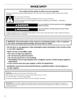
from a neighbor's phone. Follow the gas supplier's instructions. • If you cannot reach your gas supplier, call the fire department. - Installation and service must be performed by a qualified installer, service agency or the gas supplier. WARNING: Gas leaks cannot always be detected by smell - Whirlpool WFG745H0FS | Installation Guide - Page 3
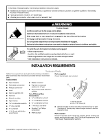
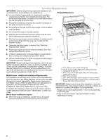
or wall. • Slide range back so rear range foot is under anti-tip bracket. • See installation instructions for details. INSTALLATION REQUIREMENTS Tools and Parts Gather the required tools and parts before starting installation. Parts supplied Read and follow the instructions provided with any - Whirlpool WFG745H0FS | Installation Guide - Page 4
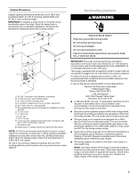
E. 25 64.6 cm) depth. Back of range to front of cooktop** F. Model/serial rating plate (located on the oven frame behind the top right side of the oven door) IMPORTANT: Range must be level after installation. Follow the instructions in the "Level Range" section. Using the cooktop as a reference - Whirlpool WFG745H0FS | Installation Guide - Page 5
installing a range hood or microwave hood combination above the range, follow the range hood or microwave hood combination installation instructions that the outlet provides 120-volt power and is correctly grounded. ■ This gas range is not required to be plugged into a GFCI (Ground-Fault Circuit - Whirlpool WFG745H0FS | Installation Guide - Page 6
edition. IMPORTANT: Leak testing of the range must be conducted according to the manufacturer's instructions. Type of Gas Natural gas: This range is factory set for use with Natural gas. See "Gas Conversions" section. The model/serial rating plate located on the oven frame behind the top right side - Whirlpool WFG745H0FS | Installation Guide - Page 7
or lower The range must be isolated from the gas supply piping system by closing its individual manual shutoff valve during any pressure testing of the gas supply piping system at test pressures equal to or less than ½ psi (3.5 kPa). INSTALLATION INSTRUCTIONS Unpack Range WARNING Excessive Weight - Whirlpool WFG745H0FS | Installation Guide - Page 8
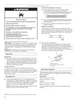
base, cardboard or hardboard to continue installing the range using the following installation instructions. Make Gas Connection WARNING Explosion Hazard Use a new CSA International approved gas supply line. Install a shut-off valve. Securely tighten all gas connections. If connected to LP, have - Whirlpool WFG745H0FS | Installation Guide - Page 9
the range. Complete Connection 1. Check that the gas pressure regulator shutoff valve is in the "on" position. B C A D F E J A. Gas pressure regulator B. 90° elbow (must have ½" male pipe thread) C. Nipple D. Union E. Black iron pipe I HG F. Manual gas shutoff valve G. ½" or ¾" gas pipe - Whirlpool WFG745H0FS | Installation Guide - Page 10
may not be installed correctly. Do not operate the range without anti-tip bracket installed and engaged. Please reference the "Assistance or Service" section of the Use and Care Guide, or the cover or "Warranty" section of the User Instructions, to contact service. Level Range Determine if you - Whirlpool WFG745H0FS | Installation Guide - Page 11
gas line. If burners do not light properly: ■ Turn cooktop control knob to the "OFF" position. ■ Check that the range "low" flame needs to be adjusted: A A. Screws B. Oven Guide or User Instructions for proper operation of the oven controls. Adjust Oven Bake Burner Flame (if needed) 1. On models - Whirlpool WFG745H0FS | Installation Guide - Page 12
(on some models) Remove all items from inside the warming drawer or premium storage drawer, and allow the range to cool completely the Use and Care Guide or User Instructions for proper operation of the oven controls. Adjust Oven Broil Burner Flame (if needed) Look through oven window to check broil - Whirlpool WFG745H0FS | Installation Guide - Page 13
grounded 3 prong outlet. ■ Electrical supply is connected. ■ See "Troubleshooting" in the Use and Care Guide or User Instructions. 8. When the range has been on for 5 minutes, check for heat. If the range is cold, turn off the range and check that the gas supply line shutoff valve is open. ■ If the - Whirlpool WFG745H0FS | Installation Guide - Page 14
personnel, authorized gas company personnel, and authorized service personnel. Failure to do so can result in death, explosion, or fire. Tip Over Hazard A child or adult can tip the range and be killed. Install anti-tip bracket to floor or wall per installation instructions. Slide range back so - Whirlpool WFG745H0FS | Installation Guide - Page 15
0.85 mm 0.70 mm L107 L99 L85 L70 NOTE: Refer to the Model Number and Serial Number Plate located on the oven frame behind the top right side of the oven door for proper sizing of spuds for each burner location. 5. Place Natural gas orifice spuds in the cardboard orifice spud holder. 6. Replace the - Whirlpool WFG745H0FS | Installation Guide - Page 16
oven orifice, and set the bake burner aside. B A A. Screw B. Bake burner 6. Use a ³⁄₈" nut driver or combination wrench and turn the Natural gas bake burner orifice spud counterclockwise to remove. The spud will be stamped with a "47." 7. Replace the "47" spud with a "56" spud. Install the LP gas - Whirlpool WFG745H0FS | Installation Guide - Page 17
not operate range without anti-tip bracket installed and engaged. Failure to follow these instructions can result in death or serious burns to children and adults. 1. Turn the manual shutoff valve to the closed position. B A C A. To range B. Manual shutoff valve "closed" position C. Gas supply line - Whirlpool WFG745H0FS | Installation Guide - Page 18
N180 N155 N140 N110 NOTE: Refer to the Model Number and Serial Number Plate located on the oven frame behind the top right side of the oven door for proper sizing of spuds for each burner location. 5. Place LP gas orifice spuds in plastic parts bag for future use and keep with package containing - Whirlpool WFG745H0FS | Installation Guide - Page 19
. Checking for proper cooktop, bake and broil burner flame is very important. Natural gas flames do not have yellow tips. 3. Refer to "Complete Installation" in the "Installation Instructions" section of this manual to complete this procedure. NOTE: Make sure to save the orifices that have just - Whirlpool WFG745H0FS | Installation Guide - Page 20
de gaz à partir du téléphone d'un voisin. Suivre ses instructions. • À défaut de joindre votre fournisseur de gaz, appeler les pompiers. - L'installation et l'entretien doivent être effectués par un installateur qualifié, une agence de service ou le fournisseur de gaz. AVERTISSEMENT : L'odorat ne - Whirlpool WFG745H0FS | Installation Guide - Page 21
personne adulte peut faire basculer la cuisinière, ce qui peut causer un décès. Fixer la bride antibasculement au plancher ou au mur, conformément aux instructions d'installation. Faire glisser de nouveau la cuisinière de façon à ce que le pied arrière de la cuisinière se trouve dans la fente - Whirlpool WFG745H0FS | Installation Guide - Page 22
and Safety, Title 24, HUD Part 280). Lorsque cette norme n'est pas applicable, l'installation doit satisfaire aux critères de la norme Standard for Manufactured Home Installations, ANSI A225.1/NFPA 501A ou aux dispositions des codes locaux. Au Canada, l'installation de cette cuisinière doit - Whirlpool WFG745H0FS | Installation Guide - Page 23
châssis du four, derrière le côté supérieur droit de la porte du four) IMPORTANT : La cuisinière doit être d'aplomb après l'installation. Suivre les instructions de la section "Réglage de l'aplomb de la cuisinière". Il n'est pas recommandé d'utiliser la table de cuisson comme référence pour établir - Whirlpool WFG745H0FS | Installation Guide - Page 24
instructions peut causer un décès, une explosion ou un incendie. Observer toutes les prescriptions des codes et règlements en vigueur. IMPORTANT : L'installation de code local, l'installation doit satisfaire aux prescriptions de la plus récente édition du : National Fuel Gas Code ANSI Z223.1 ( - Whirlpool WFG745H0FS | Installation Guide - Page 25
en gaz ■ Installer une canalisation d'alimentation en gaz rigide de ¾" (1,9 cm) jusqu'à l'emplacement d'installation de la cuisiniè de 1000 pi (304,8 m) au-dessus du niveau de la mer (pas applicable au Canada). Tests de pressurisation de la canalisation de gaz On doit tester le détendeur sous une - Whirlpool WFG745H0FS | Installation Guide - Page 26
personne adulte peut faire basculer la cuisinière, ce qui peut causer un décès. Fixer la bride antibasculement au plancher ou au mur, conformément aux instructions d'installation. Faire glisser de nouveau la cuisinière de façon à ce que le pied arrière de la cuisinière se trouve dans la fente - Whirlpool WFG745H0FS | Installation Guide - Page 27
d'expédition, sur une planche en carton ou en matériau de fibres dur pour poursuivre l'installation de la cuisinière à l'aide des instructions d'installation suivantes. B C A D F E J A. Détendeur B. Coude à 90° (avec filetage mâle de ½") C. Raccord droit D. Raccord E. Tuyau de fer noir I HG - Whirlpool WFG745H0FS | Installation Guide - Page 28
Ne pas utiliser un câble de rallonge. Le non-respect de ces instructions peut causer un décès, un incendie ou un choc électrique. A. Détendeur fente de la bride antibasculement. Vérifier que la bride antibasculement est bien installée et engagée Sur les modèles avec tiroir de remisage : 1. Retirer - Whirlpool WFG745H0FS | Installation Guide - Page 29
faire fonctionner la cuisinière si la bride antibasculement n'est pas installée et engagée. Consulter la section "Assistance ou Service" du guide d'utilisation et d'entretien, la couverture ou la section "Garantie" des instructions d'utilisation pour obtenir les coordonnées des personnes à contacter - Whirlpool WFG745H0FS | Installation Guide - Page 30
la tige de commande; ajuster les flammes à la taille désirée. 3. Réinstaller le bouton de commande. 4. Tester le fonctionnement du brûleur : faire passer pour l'allumage des brûleurs du four et du gril. Consulter le Guide d'utilisation et d'entretien pour le bon fonctionnement des commandes du four. - Whirlpool WFG745H0FS | Installation Guide - Page 31
allumage peut ne survenir qu'après 50 à 60 secondes. Consulter le Guide d'utilisation et d'entretien pour le bon fonctionnement des commandes du four. de remisage de qualité supérieure pour le retirer complètement. Réinstallation : 1. Aligner les encoches de l'avant du tiroir avec les encoches - Whirlpool WFG745H0FS | Installation Guide - Page 32
, s'assurer que le four est éteint et froid. Puis, suivre ces instructions. La porte du four est lourde. Dépose : 1. Ouvrir la porte de la butée du tiroir 2. Soulever l'avant du tiroir et retirer ce dernier. Réinstallation : 1. Soulever l'avant du tiroir et placer l'arrière du tiroir dans la cuisini - Whirlpool WFG745H0FS | Installation Guide - Page 33
1. Vérifier que toutes les pièces sont maintenant installées. S'il reste une pièce inutilisée, passer en revue d'assistance ou de service : Veuillez consulter la section "Assistance ou service" dans le Guide d'utilisation et d'entretien ou la page de couverture des instructions d'utilisation, ou - Whirlpool WFG745H0FS | Installation Guide - Page 34
personne adulte peut faire basculer la cuisinière, ce qui peut causer un décès. Fixer la bride antibasculement au plancher ou au mur, conformément aux instructions d'installation. Faire glisser de nouveau la cuisinière de façon à ce que le pied arrière de la cuisinière se trouve dans la fente - Whirlpool WFG745H0FS | Installation Guide - Page 35
faire tourner dans le sens antihoraire et soulever pour enlever le gicleur. Conserver à part le gicleur du brûleur. C A D LP C Vue de côté - l'illustration ci-dessus. 6. Réinstaller le couvercle de plastique par-dessus le capuchon du détendeur. LP B A. Gicleur B. Support du gicleur C. Vis D. É - Whirlpool WFG745H0FS | Installation Guide - Page 36
surface couverte. A B 7. Remplacer le gicleur "47" par un gicleur "56". Installer le gicleur pour gaz propane du brûleur de cuisson au four en le tournant l'avant du brûleur de cuisson au four dans l'avant du four. 9. Réinstaller le brûleur de cuisson au four avec 1 vis. 10. Positionner l'avant du - Whirlpool WFG745H0FS | Installation Guide - Page 37
personne adulte peut faire basculer la cuisinière, ce qui peut causer un décès. Fixer la bride antibasculement au plancher ou au mur, conformément aux instructions d'installation. Faire glisser de nouveau la cuisinière de façon à ce que le pied arrière de la cuisinière se trouve dans la fente - Whirlpool WFG745H0FS | Installation Guide - Page 38
antihoraire et soulever pour enlever le gicleur. Conserver à part le gicleur du brûleur. C A D B ou Quadrex®, enlever la base du brûleur. REMARQUE : Réinstaller l'une des vis à travers la table de cuisson de la remplacement des gicleurs. 38 A. Gicleur B. Support du gicleur C. Vis D. Électrode d'é - Whirlpool WFG745H0FS | Installation Guide - Page 39
surface couverte. A 7. Remplacer le gicleur "56" par un gicleur "47". Installer le gicleur pour gaz naturel du brûleur de cuisson au four en le tournant à l'avant du brûleur de cuisson au four dans l'avant du four. 9. Réinstaller le brûleur de cuisson au four avec 1 vis. 10. Positionner l'avant du - Whirlpool WFG745H0FS | Installation Guide - Page 40
pointe jaune. 3. Voir le paragraphe "Achever l'installation" de la section "Instructions d'installation" du présent manuel pour achever cette proc installer la porte du four. Voir la section "Porte du four". 9. Réinstaller les grilles du four. ©2015 All rights reserved. Used under license in Canada
-
 1
1 -
 2
2 -
 3
3 -
 4
4 -
 5
5 -
 6
6 -
 7
7 -
8
-
9
-
10
-
11
-
12
-
13
-
14
-
15
-
16
-
17
-
18
-
19
-
20
-
21
-
22
-
23
-
24
-
25
-
26
-
27
-
28
-
29
-
30
-
31
-
32
-
33
-
34
-
35
-
36
-
37
-
38
-
39
-
40
 |
 |

INSTALLATION INSTRUCTIONS
30" (76.2 CM) FREESTANDING GAS RANGES
INSTRUCTIONS D’INSTALLATION DES CUISINIÈRES À GAZ
AUTOPORTANTES DE 30" (76,2 CM)
Table of Contents/Table des matières
RANGE SAFETY
.............................................................................
2
INSTALLATION REQUIREMENTS
................................................
3
Tools and Parts
............................................................................
3
Location Requirements
................................................................
4
Electrical Requirements
...............................................................
5
Gas Supply Requirements
...........................................................
6
INSTALLATION INSTRUCTIONS
..................................................
7
Unpack Range
..............................................................................
7
Install Anti-Tip Bracket
.................................................................
8
Make Gas Connection
.................................................................
8
Verify Anti-Tip Bracket Is Installed and Engaged
......................
10
Level Range
................................................................................
10
Electronic Ignition System
.........................................................
11
Warming Drawer or Premium Storage Drawer
..........................
12
Storage Drawer
..........................................................................
13
Oven Door
..................................................................................
13
Complete Installation
.................................................................
13
GAS CONVERSIONS
....................................................................
14
LP Gas Conversion
....................................................................
14
Natural Gas Conversion
.............................................................
17
SÉCURITÉ DE LA CUISINIÈRE
...................................................
20
EXIGENCES D’INSTALLATION
...................................................
22
Outillage et pièces
......................................................................
22
Exigences d'emplacement
.........................................................
22
Spécifications électriques
..........................................................
24
Spécifications de l’alimentation en gaz
.....................................
24
INSTRUCTIONS D'INSTALLATION
............................................
26
Déballage de la cuisinière
..........................................................
26
Installation de la bride antibasculement
....................................
26
Raccordement à la canalisation de gaz
.....................................
27
Vérifier que la bride antibasculement est bien
installée et engagée
...................................................................
28
Réglage de l'aplomb de la cuisinière
.........................................
29
Système d'allumage électronique
.............................................
29
Tiroir-réchaud ou tiroir de remisage de qualité
supérieure
...................................................................................
31
Tiroir de remisage
......................................................................
32
Porte du four
..............................................................................
32
Achever l’installation
..................................................................
33
CONVERSIONS POUR CHANGEMENT DE GAZ
......................
34
Conversion pour l'alimentation au propane
..............................
34
Conversion pour l'alimentation au gaz naturel
..........................
37
IMPORTANT:
Installer:
Leave installation instructions with the homeowner.
Homeowner:
Keep installation instructions for future reference.
IMPORTANT :
Installateur :
Remettre les instructions d'installation au propriétaire.
Propriétaire :
Conserver les instructions d'installation pour référence ultérieure.
W10553363B