Whirlpool WGD9450WW Installation Instructions
Whirlpool WGD9450WW - 27" Gas Dryer Manual
 |
UPC - 883049178875
View all Whirlpool WGD9450WW manuals
Add to My Manuals
Save this manual to your list of manuals |
Whirlpool WGD9450WW manual content summary:
- Whirlpool WGD9450WW | Installation Instructions - Page 1
GAS (U.S.A. AND CANADA) ELECTRIC (CANADA ONLY) INSTRUCTIONS D'INSTALLATION DE LA SÉCHEUSE À GAZ (É.-U. ET CANADA) ÉLECTRIQUE (CANADA UNIQUEMENT) Para una version de estas intrucciones en Español, visite www.Whirlpool.com TABLE OF CONTENTS DRYER SAFETY 2 INSTALLATION REQUIREMENTS 4 Tools and Parts - Whirlpool WGD9450WW | Installation Instructions - Page 2
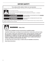
DRYER SAFETY Your safety and the safety of others are very important. We have provided many important safety messages in this manual and if you don't immediately follow instructions. WARNING You can be killed or seriously injured if you don't follow instructions. All safety messages will tell - Whirlpool WGD9450WW | Installation Instructions - Page 3
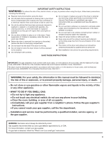
from a neighbor's phone. Follow the gas supplier's instructions. • If you cannot reach your gas supplier, call the fire department. - Installation and service must be performed by a qualified installer, service agency, or the gas supplier. WARNING: Gas leaks cannot always be detected by smell - Whirlpool WGD9450WW | Installation Instructions - Page 4
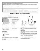
10" adjustable wrench resistant to LP gas (for gas connections) Parts supplied Non-Steam Models 4 Leveling legs Remove parts package from dryer drum. Check that all parts are included. NOTE: Do not use leveling legs supplied with dryer if installing on a pedestal. Parts needed Check local codes - Whirlpool WGD9450WW | Installation Instructions - Page 5
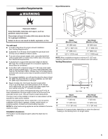
25 mm), install Extended Dryer Feet Kit, Part Number 279810. Clothes may not tumble properly and automatic sensor cycles may not operate correctly if dryer is not level. ■ For a garage installation, you will need to place the dryer at least 18" (460 mm) above the floor. If using a pedestal, you will - Whirlpool WGD9450WW | Installation Instructions - Page 6
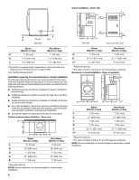
) *Required spacing **For side or bottom venting, 0" (0 mm) spacing is allowed. Recessed or closet installation - Dryer on pedestal (460 mm) A B C D* E F** Steam (Electric or Gas) Non-Steam (Electric or Gas) A 1" (25 mm) 1" (25 mm) B 27" (686 mm) 27" (686 mm) C 1" (25 mm) 1" (25 mm - Whirlpool WGD9450WW | Installation Instructions - Page 7
spacing for recessed or closet installation, with stacked washer and dryer The dimensions shown are for the recommended spacing. 48 in.2 * (310 cm2) 3"* (76 mm) C* D** E F* G H I Steam (Electric or Gas) Non-Steam (Electric or Gas) A* 7" (178 mm) B* 7" (178 mm) C* 9" (229 mm - Whirlpool WGD9450WW | Installation Instructions - Page 8
electrician or service representative or personnel if you are in doubt as to whether the dryer is properly grounded. Do not modify the plug provided with the dryer: if it will not fit the outlet, have a proper outlet installed by a qualified electrician. SAVE THESE INSTRUCTIONS 4-wire receptacle - Whirlpool WGD9450WW | Installation Instructions - Page 9
"Assistance or Service" section. LP gas conversion: Conversion must be made by a qualified technician. No attempt shall be made to convert the appliance from the gas specified on the model/serial rating plate for use with a different gas without consulting your gas company. Gas supply line ■ Must - Whirlpool WGD9450WW | Installation Instructions - Page 10
mm) 1½" A (38 mm) A. 1/2" NPT gas supply line B. 3/8" NPT dryer pipe *NOTE: If the dryer is mounted on a pedestal, the gas pipe height must be an additional 10" (254 mm) or 15.5" (394 mm) from the floor, depending on the pedestal model. For a garage installation, the gas pipe height must be an - Whirlpool WGD9450WW | Installation Instructions - Page 11
Whirlpool Service. For more information, see the "Assistance or Service" section. Rigid metal vent ■ For best supported when the dryer is in its final location. ■ Remove excess flexible metal vent to avoid sagging and kinking that may result in reduced airflow and poor performance. ■ Do not install - Whirlpool WGD9450WW | Installation Instructions - Page 12
installation NOTE: The following kits for close-clearance alternate installations are available for purchase. Please see the "Assistance or Service" section to order. ■ Over-the-Top Installation: Part Number 4396028 ■ Periscope Installation (For use with dryer vent to wall vent mismatch): Part - Whirlpool WGD9450WW | Installation Instructions - Page 13
flexible gas line. 4. Once the exhaust vent connection is made, remove the corner posts and cardboard. CONNECT INLET HOSE (STEAM MODELS) The dryer must be connected to the cold water faucet using the new inlet hoses. Do not use old hoses. 1. Turn cold water faucet off and remove washer inlet hose - Whirlpool WGD9450WW | Installation Instructions - Page 14
connector. 7. Attach washer cold inlet hose to Dryer Use." Electric Models Only 9. For power supply cord installation, plug into a grounded outlet. Gas Models Only: 10. Check that gas supply is on. 11. Check for leaks. Steam Models dryer. Over time, the buildup of lime scale may clog different parts - Whirlpool WGD9450WW | Installation Instructions - Page 15
for service. Dryer displaying code message ■ "PF" (power failure), check the following: Was the drying cycle interrupted by a power failure? Press and hold START/PAUSE to restart the dryer. ■ "L2" Diagnostic Code (low or no line voltage condition): The drum will turn, but there may be a problem - Whirlpool WGD9450WW | Installation Instructions - Page 16
or replace exhaust vent with heavy metal or flexible metal vent. See the Installation Instructions. ■ Are fabric softener sheets blocking the grille? Use only one fabric softener sheet, and use it only once. ■ Is the dryer located in a closet? Closet doors must have ventilation openings at the top - Whirlpool WGD9450WW | Installation Instructions - Page 17
: DANGER Risque possible de décès ou de blessure grave si vous ne suivez pas immédiatement les instructions. AVERTISSEMENT Risque possible de décès ou de blessure grave si vous ne suivez pas les instructions. Tous les messages de sécurité vous diront quel est le danger potentiel et vous disent - Whirlpool WGD9450WW | Installation Instructions - Page 18
, ou en l'absence de codes locaux, au Code canadien de l'électricité, CSA C22.1. Dans l'État du Massachusetts, les instructions d'installation suivantes sont applicables : ■ Les travaux d'installation et réparation doivent être exécutés par un plombier ou tuyauteur qualifié ou licencié, ou par le - Whirlpool WGD9450WW | Installation Instructions - Page 19
service" de votre Guide d'utilisation et d'entretien. Équipement facultatif Consulter votre Guide d'utilisation et d'entretien pour en savoir plus sur les accessoires disponibles pour votre sécheuse. Exigences d'emplacement Installations plancher robuste capable de supporter un poids total (sécheuse - Whirlpool WGD9450WW | Installation Instructions - Page 20
mm) C 3 3/8" (86 mm) Non-Steam (Electric or Gas) 1" (25 mm) 7 5/8" (194 mm) 3 3/8" (86 mm) * La dimension A est approximative et dépend de la visibilité du losange sur le pied de nivellement. Voir "Exigences concernant l'évacuation". Espacement pour une installation dans un encastrement ou dans - Whirlpool WGD9450WW | Installation Instructions - Page 21
une évacuation par le côté ou par le fond, un espacement de 0" (0 mm) est permis. REMARQUE : Certains modèles ne sont pas recommandés pour une installation dans un encastrement ou un placard. (460 mm) A* B C** Vue latérale Porte de placard avec orifices d'entrée d'air Vapeur (électrique ou à gaz - Whirlpool WGD9450WW | Installation Instructions - Page 22
on doit prévoir des ouvertures minimum d'entrée d'air au sommet du placard. A* B* Espacement recommandé pour une installation dans un encastrement ou dans un placard, avec laveuse et sécheuse superposées Les dimensions indiquées sont pour l'espacement recommandé. 48 in.2 * (310 cm2) 3"* (76 mm - Whirlpool WGD9450WW | Installation Instructions - Page 23
Canadian Standards Association, 178 Rexdale Blvd., Toronto, ON M9W 1R3 CANADA. ■ L'appareil doit être alimenté uniquement par une alimentation électrique courant, demander à un électricien qualifié d'installer une prise de courant appropriée. CONSERVEZ CES INSTRUCTIONS Prise murale à 4 fils (14-30R - Whirlpool WGD9450WW | Installation Instructions - Page 24
é. Le non-respect de ces instructions peut causer un décès, un explosion (propane ou butane), avec conversion appropriée. ■ Cette sécheuse Canada : Un robinet d'arrêt manuel individuel doit être installé à six (6) pieds (1,8 m) de la sécheuse conformément au Natural Gas and Propane Installation - Whirlpool WGD9450WW | Installation Instructions - Page 25
une installation au-dessus de 10 000 pi (3 048 m), une réduction de 4 % du débit thermique (en BTU) raccordement peut varier, selon le type, la dimension et l'emplacement de l'alimentation. D A B . Le non-respect de ces instructions peut causer un décès, un incendie ou un choc électrique. - Whirlpool WGD9450WW | Installation Instructions - Page 26
à un électricien qualifié d'installer une prise de courant appropriée. CONSERVEZ CES INSTRUCTIONS ÉVACUATION Exigences concernant l'évacuation AVERTISSEMENT ou en appelant l'assistance Whirlpool. Pour plus de renseignements, consulter la section "Assistance ou service". Conduit métallique rigide ■ - Whirlpool WGD9450WW | Installation Instructions - Page 27
charge H E. Brides de serrage F. Conduit métallique rigide ou souple G. Longueur de conduit nécessaire pour raccorder les coudes H. Bouche de décharge Installations d'évacuation facultatives Cette sécheuse peut être convertie pour une évacuation par le côté droit, le côté gauche ou par le bas. Si - Whirlpool WGD9450WW | Installation Instructions - Page 28
Voir les instructions du fabricant. A. Installation au-dessus de la sécheuse (également disponible avec un coude décalé) B. Installation avec périscope REMARQUE : On peut acheter les trousses suivantes pour les installations où le dégagement est réduit. Voir la section "Assistance ou service" pour - Whirlpool WGD9450WW | Installation Instructions - Page 29
ou plus de personnes pour déplacer et installer la sécheuse. Le non-respect de cette instruction peut causer une blessure au dos ou d' d'eau froide à l'aide des nouveaux tuyaux d'alimentation. Ne pas utiliser de tuyaux usagés. 1. Arrêter le robinet d'eau froide et retirer le tuyau d'alimentation de - Whirlpool WGD9450WW | Installation Instructions - Page 30
é pour ajuster les pieds vers le haut ou vers le bas, et vérifier à nouveau si elle est d'aplomb. ACHEVER L'INSTALLATION 1. Vérifier que toutes les pièces sont maintenant installées. S'il reste une pièce, passer en revue les différentes étapes pour découvrir laquelle aurait été oubliée. 2. Vérifier - Whirlpool WGD9450WW | Installation Instructions - Page 31
cheuse est fermée. Cette sécheuse exécute automatiquement une routine de diagnostic d'installation au début de son premier programme. Si vous recevez un code d' , ce qui vous évitera peut-être le coût d'une visite de service... Fonctionnement de la sécheuse Le sécheuse ne fonctionne pas ■ Un fusible - Whirlpool WGD9450WW | Installation Instructions - Page 32
à l'avant de la sécheuse, et pour la plupart des installations, un espacement minimum de 5" (127 mm) est nécessaire à l'arrière de la sécheuse. Voir "Instructions d'installation". W10255469B W10259188B - SP © 2009 Whirlpool Corporation. All rights reserved. Tous droits réservés. 4/09 Printed
-
 1
1 -
 2
2 -
 3
3 -
 4
4 -
 5
5 -
 6
6 -
 7
7 -
8
-
9
-
10
-
11
-
12
-
13
-
14
-
15
-
16
-
17
-
18
-
19
-
20
-
21
-
22
-
23
-
24
-
25
-
26
-
27
-
28
-
29
-
30
-
31
-
32
 |
 |

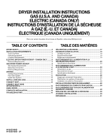
DRYER INSTALLATION INSTRUCTIONS
GAS (U.S.A. AND CANADA)
ELECTRIC (CANADA ONLY)
INSTRUCTIONS D'INSTALLATION DE LA SÉCHEUSE
À GAZ (É.-U. ET CANADA)
ÉLECTRIQUE (CANADA UNIQUEMENT)
W10255469B
W10259188B - SP
Para una version de estas intrucciones en Español, visite www.Whirlpool.com
TABLE OF CONTENTS
DRYER SAFETY
..............................................................................
2
INSTALLATION REQUIREMENTS
................................................
4
Tools and Parts
............................................................................
4
Optional Equipment
.....................................................................
4
Location Requirements
................................................................
5
ELECTRIC DRYER POWER HOOKUP – CANADA ONLY
..........
8
Electrical Requirements
...............................................................
8
GAS DRYER POWER HOOKUP
....................................................
9
Gas Supply Requirements
...........................................................
9
Make Gas Connection
...............................................................
10
Electrical Requirements
.............................................................
10
VENTING
.......................................................................................
11
Venting Requirements
................................................................
11
Plan Vent System
.......................................................................
12
Install Vent System
.....................................................................
13
INSTALL LEVELING LEGS
...........................................................
13
CONNECT VENT
...........................................................................
13
CONNECT INLET HOSE
(STEAM MODELS)
........................................................................
13
LEVEL DRYER
..............................................................................
14
COMPLETE INSTALLATION
.......................................................
14
TROUBLESHOOTING
..................................................................
15
TABLE DES MATIÈRES
SÉCURITÉ DE LA SÉCHEUSE
....................................................
17
EXIGENCES D'INSTALLATION
...................................................
19
Outillage et pièces
......................................................................
19
Équipement facultatif
.................................................................
19
Exigences d'emplacement
.........................................................
19
RACCORDEMENT DE L'ALIMENTATION À LA
SÉCHEUSE ÉLECTRIQUE
...........................................................
23
Spécifications électriques
..........................................................
23
RACCORDEMENT DE L'ALIMENTATION
À LA SÉCHEUSE À GAZ
..............................................................
24
Alimentation en gaz
....................................................................
24
Raccordement au gaz
................................................................
25
Spécifications électriques
..........................................................
25
ÉVACUATION
................................................................................
26
Exigences concernant l'évacuation
...........................................
26
Planification du système d'évacuation
......................................
27
Installation du système d'évacuation
.........................................
28
INSTALLATION DES PIEDS DE NIVELLEMENT
........................
29
RACCORDEMENT DU CONDUIT D'ÉVACUATION
..................
29
RACCORDEMENT DES TUYAUX D'ALIMENTATION
(MODÈLES À VAPEUR)
................................................................
29
RÉGLAGE DE L'APLOMB DE LA SÉCHEUSE
...........................
30
ACHEVER L'INSTALLATION
.......................................................
30
DÉPANNAGE
.................................................................................
31