Whirlpool WMH31017AW Installation Instructions - Page 6
Locate Wall Studs - mounting plate
 |
View all Whirlpool WMH31017AW manuals
Add to My Manuals
Save this manual to your list of manuals |
Page 6 highlights
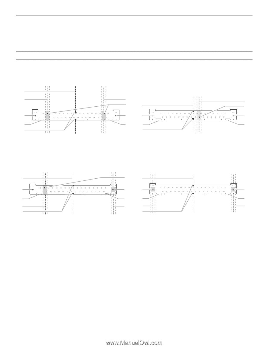
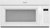
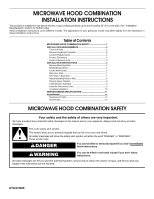
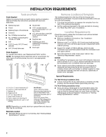
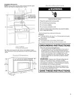
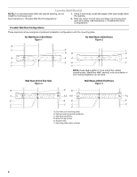
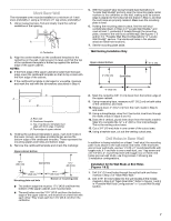
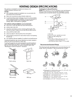
Locate Wall Stud(s) NOTE: If no wall studs exist within the cabinet opening, do not install the microwave oven. 1. Using a stud finder, locate the edges of the wall stud(s) within the opening. See illustrations in "Possible Wall Stud Configurations." 2. Mark the center of each stud, and draw a plumb line down each stud center. See illustrations in "Possible Wall Stud Configurations." Possible Wall Stud Configurations These depictions show examples of preferred installation configurations with the mounting plate. No Wall Studs at End Holes Figure 1 No Wall Studs at End Holes Figure 2 B C C C D B D A A A A E E E E F F NOTE: If wall stud is within 6" (15.2 cm) of the vertical centerline (see "Mark Rear Wall" section), only recirculation or roof venting installation can be done. Wall Stud at One End Hole Figure 3 Wall Studs at Both End Holes Figure 4 B D B A A,D A,D A,D E E E E C C C C F F A. End holes (on mounting plate) B. Cabinet opening vertical centerline C. Wall stud centerlines D. Holes for lag screws E. Support tabs F. Mounting plate center markers 6
-
 1
1 -
 2
2 -
 3
3 -
 4
4 -
 5
5 -
 6
6 -
 7
7 -
 8
8 -
 9
9 -
 10
10 -
 11
11 -
 12
12
 |
 |