Whirlpool WMH31017FS Installation Guide
Whirlpool WMH31017FS Manual
 |
View all Whirlpool WMH31017FS manuals
Add to My Manuals
Save this manual to your list of manuals |
Whirlpool WMH31017FS manual content summary:
- Whirlpool WMH31017FS | Installation Guide - Page 1
in these installation instructions. Table of Contents MICROWAVE HOOD COMBINATION SAFETY 1 INSTALLATION REQUIREMENTS 2 Tools and Parts 2 Remove Cardboard Template 2 Location Requirements 2 Product Dimensions 3 Electrical Requirements 3 INSTALLATION INSTRUCTIONS 4 Remove Mounting Plate - Whirlpool WMH31017FS | Installation Guide - Page 2
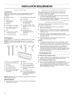
■■ Mounting plate (attached to back of microwave oven) ■■ Cardboard template (part of packaging) ■■ Aluminum grease filters ■■ Charcoal filters (Depending on model, charcoal filters may not be included. See User Instructions.) NOTE: Depending on model, aluminum grease filter and charcoal filter may - Whirlpool WMH31017FS | Installation Guide - Page 3
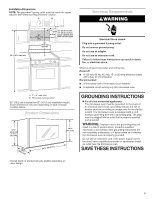
circuit breaker. Recommended: ■■ A time-delay fuse or time-delay circuit breaker. ■■ A separate circuit serving only this microwave oven. A. 2" x 4" wall stud B. Grounded 3 prong outlet *30" (76.2 cm) is typical for 66" (167.6 cm) installation height. Exact dimensions may vary depending on type of - Whirlpool WMH31017FS | Installation Guide - Page 4
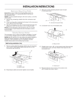
INSTALLATION INSTRUCTIONS Remove Mounting Plate Depending on your model, the mounting plate may be in the foam packaging, or it may be attached to the back of the microwave oven. NOTE: To avoid possible damage to the work surface, cover the work surface. 1. Remove any remaining contents from the - Whirlpool WMH31017FS | Installation Guide - Page 5
. Make sure damper plate tabs are inserted into the slots in the top of the microwave oven. A B C 6. Reattach blower motor to back of microwave oven with 2 screws removed in Step 3 of "Wall Venting Installation Only." Securely tighten screws. NOTE: If blower motor is not correctly oriented, the - Whirlpool WMH31017FS | Installation Guide - Page 6
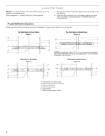
Wall Stud(s) NOTE: If no wall studs exist within the cabinet opening, do not install the microwave oven. See illustrations in "Possible Wall Stud Configurations." 1. Using a stud finder, locate the edges of the wall stud(s) within the opening. 2. Mark the center of each stud, and draw a plumb - Whirlpool WMH31017FS | Installation Guide - Page 7
on a level line with each other. They must each be 14¹⁄₈" (35.9 cm) from the centerline. 5. With the support tabs facing forward (see illustrations in "Locate Wall Stud(s)" section), align the mounting plate center markers to the centerline on the wall, making sure its bottom edge is aligned to the - Whirlpool WMH31017FS | Installation Guide - Page 8
" in "Locate Wall Stud(s)" section. No Wall Studs at End Holes (Figures 1 and 2) NOTE: The mounting plate must guides. ■■ If the wall behind the microwave oven (as installed) has a partial wall covering (for example, tile backsplash), be sure the "Rear Wall" arrows align to the thickest part - Whirlpool WMH31017FS | Installation Guide - Page 9
needs to be installed around the supply microwave oven door is closed and taped shut. 3. Using 2 or more people, lift microwave oven and hang it on support tabs at the bottom of mounting plate. NOTE: To avoid damage to the microwave oven, do not grip or use the door or door handle while the microwave - Whirlpool WMH31017FS | Installation Guide - Page 10
Replace the fuse or reset the circuit breaker. If the problem continues, call an electrician. ■■ Check that the power supply cord is plugged into a grounded 3 prong outlet. ■■ See the User Instructions for troubleshooting information. Installation is now complete. Save Installation Instructions for - Whirlpool WMH31017FS | Installation Guide - Page 11
VENTING DESIGN SPECIFICATIONS This section is intended for architectural designer and builder/ contractor reference only. NOTES: ■■ Vent materials needed for installation are not provided with microwave hood combination. ■■ We do not recommend using a flexible metal vent. ■■ To avoid possible - Whirlpool WMH31017FS | Installation Guide - Page 12
installation hardware needs to be replaced, call us at our toll free number listed in the User Guide. Following is a list of available replacement parts. You will need your model number located on the front facing of the microwave oven opening, behind the door. ■■ Damper Assembly ■■ Mounting Plate
-
 1
1 -
 2
2 -
 3
3 -
 4
4 -
 5
5 -
 6
6 -
 7
7 -
8
-
9
-
10
-
11
-
12
 |
 |
MICROWAVE HOOD COMBINATION
INSTALLATION INSTRUCTIONS
This product is suitable for use above electric or gas cooking products up to and including 36" (91.4 cm) wide. See “Installation
Requirements” section for further notes.
These installation instructions cover different models. The appearance of your particular model may differ slightly from the illustration
in these installation instructions.
MICROWAVE HOOD COMBINATION SAFETY
You can be killed or seriously injured if you don't immediately
You
can be killed or seriously injured if you don't follow
All safety messages will tell you what the potential hazard is, tell you how to reduce the chance of injury, and tell you what can
happen if the instructions are not followed.
Your safety and the safety of others are very important.
We have provided many important safety messages in this manual and on your appliance. Always read and obey all safety
messages.
This is the safety alert symbol.
This symbol alerts you to potential hazards that can kill or hurt you and others.
All safety messages will follow the safety alert symbol and either the word “DANGER” or “WARNING.”
These words mean:
follow instructions.
instructions.
DANGER
WARNING
MICROWAVE HOOD COMBINATION SAFETY
............................
1
INSTALLATION REQUIREMENTS
.................................................
2
Tools and Parts
.............................................................................
2
Remove Cardboard Template
......................................................
2
Location Requirements
................................................................
2
Product Dimensions
.....................................................................
3
Electrical Requirements
...............................................................
3
INSTALLATION INSTRUCTIONS
...................................................
4
Remove Mounting Plate
...............................................................
4
Rotate Blower Motor
....................................................................
4
Locate Wall Stud(s)
......................................................................
6
Mark Rear Wall
.............................................................................
7
Drill Holes in Rear Wall
.................................................................
7
Attach Mounting Plate to Wall
.....................................................
8
Prepare Upper Cabinet
................................................................
8
Install Damper Assembly
.............................................................
9
Install the Microwave Oven
..........................................................
9
Complete Installation
.................................................................
10
VENTING DESIGN SPECIFICATIONS
.........................................
11
ASSISTANCE
................................................................................
12
Replacement Parts
.....................................................................
12
Accessories
................................................................................
12
Table of Contents
W10823831A