Whirlpool WMH32517AW Installation Instructions - Page 7
Mark Rear Wall, Drill Holes in Rear Wall
 |
View all Whirlpool WMH32517AW manuals
Add to My Manuals
Save this manual to your list of manuals |
Page 7 highlights
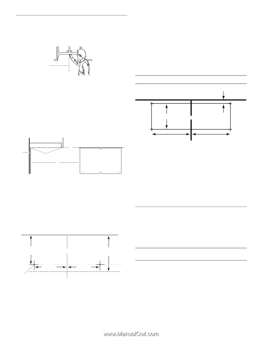
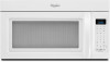
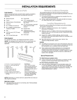
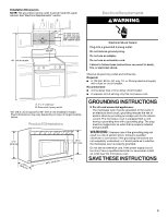
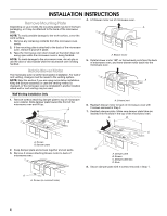
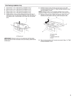
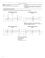
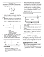
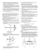
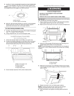
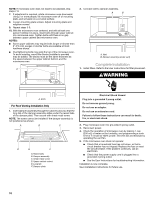
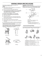
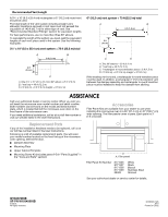
Mark Rear Wall The microwave oven must be installed on a minimum of 1 wall stud, preferably 2, using a minimum of 1 lag screw, preferably 2. 1. Using measuring tape, find and clearly mark the vertical centerline of the opening. A A. Centerline 2. Align the center markers on the cardboard template to the centerline on the wall, making sure it is level, and that the top of the cardboard template is butted up against the bottom edge of the upper cabinet. NOTES: ■ If the front edge of the upper cabinet is lower than the back edge, lower the cardboard template so that its top is level with the front edge of the cabinet. ■ If the cardboard template is damaged or unusable, measure and mark the wall with the dimensions described in Step 4. D A C B A. Rear wall B. Cardboard template C. Top of cardboard template must align with front edge of cabinet. D. Front edge of upper cabinet 3. Holding the cardboard template in place, mark both holes in the lower corners, and draw a horizontal line across the bottom edge of the cardboard template. These represent the mounting plate's end holes and bottom edge. 4. Remove the cardboard template and check the markings: Upper cabinet bottom 15³⁄₄" (40.0 cm) Centerline 17¹⁄₄" (43.8 cm) 14¹⁄₈" (35.9 cm) Mounting plate end hole 14¹⁄₈" (35.9 cm) Bottom of mounting plate ■ The bottom edge line must be 17¹⁄₄" (43.8 cm) from the bottom of the upper cabinet, and must be level. ■ The end holes must be 15³⁄₄" (40.0 cm) from the bottom edge of the upper cabinet, and must be on a level line with each other. They must each be 14¹⁄₈" (35.9 cm) from the centerline. 5. With the support tabs facing forward (see illustrations in "Locate Wall Stud(s)" section), align the mounting plate center markers to the centerline on the wall, making sure its bottom edge is aligned to the horizontal line drawn in Step 3, and that the end holes are properly marked. Make sure the mounting plate is level. 6. Holding the mounting plate in place, find the wall stud centerline(s) drawn in Step 2 of "Locate Wall Stud(s)," and mark at least 1, preferably 2 hole(s) through the mounting plate, closest to the wall stud centerline(s). See figures 1, 2 and/or 3 in "Possible Wall Stud Configurations" in "Locate Wall Stud(s)" section. The blackened holes in the shaded areas are ideal hole locations. 7. Set the mounting plate aside. Wall Venting Installation Only Upper cabinet bottom ³⁄₈" (1 cm) 4" (10.2 cm) Centerline 6" (15.2 cm) 6" (15.2 cm) 8. Mark the centerline 3/8" (1 cm) down from the bottom edge of the upper cabinet. 9. Using measuring tape, measure out 6" (15.2 cm) on both sides of the centerline, and mark. 10. Measure down 4" (10.2 cm) from the mark made in Step 8, and mark. 11. Using a straightedge, draw the 2 horizontal, level lines through the marks made in steps 8 and 10. 12. Draw the 2 vertical, plumb lines down from the marks made in Step 9 to complete the 12" x 4" (30.5 x 10.2 cm) rectangle. This is the venting cutout area. 13. Cut a 3/4" (19 mm) hole in one corner of the cutout area. 14. Using a keyhole saw, cut out the venting cutout area. Drill Holes in Rear Wall In addition to being installed on at least 1 wall stud, the mounting plate must attach to the wall at both end holes. If the end holes are not over wall studs, use two 1/4-20 x 3" round-head bolts with toggle nuts; if 1 end hole is over a wall stud, use 1 lag screw and one 1/4-20 x 3" round-head bolt with toggle nut; or if both end holes are over wall studs, use 2 lag screws. Following are 3 installation configurations. Installation for No Wall Studs at End Holes (Figures 1 & 2) 1. Drill 3/4" (19 mm) holes through the wall at both end holes marked in Step 3 of "Mark Rear Wall." 2. Drill 3/16" (5 mm) hole(s) into the wall stud(s) at the hole(s) marked in Step 6 of "Mark Rear Wall." Refer to figures 1 and 2 in "Possible Wall Stud Configurations" in "Locate Wall Stud(s)" section. 7
-
 1
1 -
 2
2 -
 3
3 -
 4
4 -
 5
5 -
 6
6 -
 7
7 -
 8
8 -
 9
9 -
 10
10 -
 11
11 -
 12
12
 |
 |