Whirlpool WOS51EC0AS Installation Guide
Whirlpool WOS51EC0AS Manual
 |
View all Whirlpool WOS51EC0AS manuals
Add to My Manuals
Save this manual to your list of manuals |
Whirlpool WOS51EC0AS manual content summary:
- Whirlpool WOS51EC0AS | Installation Guide - Page 1
.2 CM) ELECTRIC SINGLE AND DOUBLE BUILT-IN OVEN INSTRUCTIONS D'INSTALLATION FOUR ÉLECTRIQUE ENCASTRÉ 27" (68,6 CM) ET 30" (76,2 CM) - SIMPLE ET DOUBLE Table of Contents/Table des matières BUILT-IN OVEN SAFETY 1 SÉCURITÉ DU FOUR ENCASTR 17 INSTALLATION REQUIREMENTS 2 Tools and Parts 2 Location - Whirlpool WOS51EC0AS | Installation Guide - Page 2
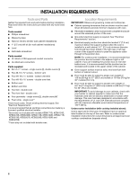
. **Foam strip not included with double oven. Location Requirements IMPORTANT: Observe all governing codes and ordinances. ■ Cabinet opening dimensions that are shown must be used. Given dimensions provide minimum clearance with oven. ■ Recessed installation area must provide complete enclosure - Whirlpool WOS51EC0AS | Installation Guide - Page 3
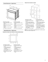
cm) recessed height D. 23¹⁄₄" (59.1 cm) max. recessed depth E. 30" (76.2 cm) overall width Cabinet Dimensions - Single Ovens Single Oven Undercounter (without cooktop installed above) A B C 27" (68.6 cm) models A. 27" (68.6 cm) min. cabinet width B. 1" (2.5 cm) top of cutout to bottom of upper - Whirlpool WOS51EC0AS | Installation Guide - Page 4
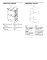
Product Dimensions - Double Ovens B Cabinet Dimensions - Double Ovens Double Ovens Installed in Cabinet A A C B D F E D 27" (68.6 cm) models A. 51 130.0 cm) max. overall height B. 25 64.6 cm) max. recessed width C. 48 124.0 cm) recessed height D. 23¹⁄₄" (59.1 cm) max. recessed depth E. 27" - Whirlpool WOS51EC0AS | Installation Guide - Page 5
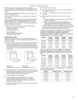
Connection To properly install your oven, you must determine the type of electrical connection you will be using and follow the instructions provided for it here. Voltage 240 VAC Single Thermal 3690 W Single Convect 3720 W Double Thermal 7370 W Double Convect 7400 W ■ Oven must be connected - Whirlpool WOS51EC0AS | Installation Guide - Page 6
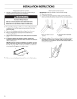
INSTALLATION INSTRUCTIONS Prepare Built-In Oven 1. Decide on the final location for the oven. Avoid drilling or cutting into house wiring during installation. WARNING Excessive Weight Hazard Use two or more people to move and install oven. Failure to do so can result in back or other injury. - Whirlpool WOS51EC0AS | Installation Guide - Page 7
Feet for Multiple Cabinet Cutout Heights Single Ovens The positioning of the oven feet allow a single oven to be installed in a cutout height between 26 68.4 cm) and 29 74.8 cm). Refer to the following instructions to position the feet for the size of your cabinet cutout. 2. Remove the foot from - Whirlpool WOS51EC0AS | Installation Guide - Page 8
side of the foot is positioned toward the top of the oven. Double Ovens The positioning of the oven feet allow a double oven to be installed in a cutout height between 48⁷⁄₈" (124.1 cm) and 52 132.6 cm). Refer to the following instructions to position the feet for the size of your cabinet cutout - Whirlpool WOS51EC0AS | Installation Guide - Page 9
"Make Electrical Connection" section. Cutout Height is between 51 130.0 cm) and 52 132.6 cm) 1. Using 2 or more people, place the oven on its back on a covered surface. 2. Install a foot on the left rear spacer using a #8-18 x ³⁄₈" screw. NOTE: Position the foot so the short side of the foot is - Whirlpool WOS51EC0AS | Installation Guide - Page 10
Electrical Connection" section. Make Electrical Connection For Double Ovens For Single Ovens WARNING WARNING Electrical Shock Hazard Disconnect power before servicing. Use 8 gauge solid copper wire. Electrically ground oven. Failure to follow these instructions can result in death, fire, or - Whirlpool WOS51EC0AS | Installation Guide - Page 11
using a UL listed wire connector. 5. Connect the green (or bare) ground wire (H) from the oven cable to the green (or bare) ground wire (in the junction box) using a UL listed wire connector. 6. Install junction box cover. 3-Wire Cable from Home Power Supply - U.S. Only IMPORTANT: Use the 3-wire - Whirlpool WOS51EC0AS | Installation Guide - Page 12
grommet. Do not overtighten screws. 6. On models with the foot positioned with the long side of the foot facing toward the top of the oven, the oven vent is taped to the side of the oven. See the following instructions to install. ■ Align vent tab (B) with oven frame (A) as shown. ■ Using one #8-18 - Whirlpool WOS51EC0AS | Installation Guide - Page 13
top of the oven, the bottom vent trim must also be installed. See the following instructions to install. ■ Position the bottom vent trim (B) on the vent (C). ■ Install the bottom vent trim (B) to the vent (C) using two #8-18 x ¹⁄₄" screws on each side. NOTE: On 27" (68.6 cm) models, only one #8-18 - Whirlpool WOS51EC0AS | Installation Guide - Page 14
available. For more information, read the Use and Care Guide. 3. Press BROIL on single oven models. NOTE: Press UPPER BROIL or LOWER BROIL on double oven models. 4. Set the temperature. ■ See "Troubleshooting" section in the Use and Care Guide. 6. When oven has been on for 5 minutes, feel for heat - Whirlpool WOS51EC0AS | Installation Guide - Page 15
Notes 15 - Whirlpool WOS51EC0AS | Installation Guide - Page 16
Notes 16 - Whirlpool WOS51EC0AS | Installation Guide - Page 17
pièces Rassembler les outils et composants nécessaires avant d'entreprendre l'installation. Lire et observer les instructions fournies avec chacun des outils de la liste ci-dessous. Pièces fournies ■ Vis n° 8-14 x 1" - Four simple (2), four double (4) ■ Deux vis n° 8-18 x vent inférieur Outils - Whirlpool WOS51EC0AS | Installation Guide - Page 18
■ Le plancher doit pouvoir supporter le poids d'un four double de 251 lb (114 kg installée au-dessus) : Les fours homologués pour ce type d'installation comportent une étiquette d'homologation placée sur le dessus. Voir les E instructions d'installation du plan de travail au sujet des dimensions - Whirlpool WOS51EC0AS | Installation Guide - Page 19
Fours simples installés dans un placard A Dimensions du produit - Fours doubles. B B D F G E C A C Modèles de 27" (68,6 cm) A. Largeur du placard 27" (68,6 cm) min. B. 1" (2,5 cm) entre le sommet de l'ouverture découpée et le bas de la - Whirlpool WOS51EC0AS | Installation Guide - Page 20
Dimensions du placard - Fours doubles Fours doubles installés dans un placard A B D F G E C Modèles de 27" (68,6 cm) A. Largeur Raccordement électrique Pour installer le four correctement, il faut établir le type de raccords électriques que l'on utilisera et suivre les instructions indiquées ici. - Whirlpool WOS51EC0AS | Installation Guide - Page 21
quipé d'un câblage en aluminium, suivre les instructions suivantes : 1. Connecter une section de câble les WOS51EC7A, WOS51EC0A, WOD51EC7A, WOD51EC0A, WOS92EC7A, WOS92EC0A, WOD93EC7A, au tableau cidessous. Tension Simple Simple À Double Double À Thermique convection Thermique convection 240 VCA - Whirlpool WOS51EC0AS | Installation Guide - Page 22
. AVERTISSEMENT Risque du poids excessif Utiliser deux ou plus de personnes pour déplacer et installer le four. Le non-respect de cette instruction peut causer une blessure au dos ou d'autre blessure. Dépose de la porte du four IMPORTANT : Employer les deux mains pour enlever la/les porte - Whirlpool WOS51EC0AS | Installation Guide - Page 23
hauteur différente Four simple En modifiant le positionnement des pieds du four, on peut installer un four simple dans une cavité d'encastrement d'une hauteur comprise entre 26 68,4 cm) et 29 74,8 cm). Consulter les instructions suivantes pour adapter la position des pieds à la taille de la cavit - Whirlpool WOS51EC0AS | Installation Guide - Page 24
En modifiant le positionnement des pieds du four, on peut installer un four double dans une cavité d'encastrement d'une hauteur comprise entre 48⁷⁄₈" (124,1 cm) et 52 132,6 cm). Consulter les instructions suivantes pour adapter la position des pieds à la taille de la cavité d'encastrement. La - Whirlpool WOS51EC0AS | Installation Guide - Page 25
entre 51 130,0 cm) et 52 132,6 cm) 1. À l'aide d'au moins 2 personnes, placer le four sur sa partie arrière, sur une surface couverte. 2. Installer un pied sur la cale d'espacement arrière gauche avec une vis n° 8-18 x ³⁄₈". REMARQUE : Positionner le pied de façon à ce que le côté court du - Whirlpool WOS51EC0AS | Installation Guide - Page 26
orienté vers le four, tel qu'illustré. 5. De la même manière installer un pied avant sur l'avant droit du four. 6. À l'aide d'au moins ³⁄₈" C. Cale d'espacement Fours doubles 7. Passer à la section " la terre. Le non-respect de ces instructions peut causer un décès, un incendie ou un - Whirlpool WOS51EC0AS | Installation Guide - Page 27
États-Unis lorsque les codes locaux ne permettent pas la mise à la terre par l'intermédiaire du conducteur neutre, en cas de nouvelle installation avec alimentation par un circuit secondaire (1996 NEC), dans les résidences mobiles et les véhicules récréatifs, dans les nouvelles constructions, et au - Whirlpool WOS51EC0AS | Installation Guide - Page 28
est orienté vers le sommet du four, l'évent du four est fixé au côté du four par du ruban adhésif. Pour l'installation, procéder selon les instructions suivantes. ■ Aligner le support de l'évent (B) avec le châssis du four (A) comme illustré. ■ Avec une vis n° 8-18 x ³⁄₈" (D) pour chaque côté du - Whirlpool WOS51EC0AS | Installation Guide - Page 29
l'évent inférieur doit également être installée. Pour l'installation, procéder selon les instructions suivantes. ■ Placer la garniture de conduit service" du guide d'utilisation et d'entretien ou contacter le marchand auprès duquel le four a été acheté. A B E D C A. Châssis du four B. Support - Whirlpool WOS51EC0AS | Installation Guide - Page 30
le four et contacter un technicien qualifié. 7. Pour les fours doubles, appuyer sur UPPER CANCEL/ LOWER CANCEL (annulation four supérieur/ Si vous avez besoin d'assistance ou de service : Consulter la section "Assistance ou service" du Guide d'utilisation et d'entretien ou contacter le marchand - Whirlpool WOS51EC0AS | Installation Guide - Page 31
Notes 31 - Whirlpool WOS51EC0AS | Installation Guide - Page 32
W10351242B © 2012. All rights reserved. Tous droits réservés. 2/12 Printed in U.S.A. Imprimé aux É.-U.
-
 1
1 -
 2
2 -
 3
3 -
 4
4 -
 5
5 -
 6
6 -
 7
7 -
8
-
9
-
10
-
11
-
12
-
13
-
14
-
15
-
16
-
17
-
18
-
19
-
20
-
21
-
22
-
23
-
24
-
25
-
26
-
27
-
28
-
29
-
30
-
31
-
32
 |
 |

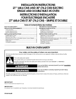
INSTALLATION INSTRUCTIONS
27 " (68.6 CM) AND 30" (76.2 CM) ELECTRIC
SINGLE AND DOUBLE BUILT-IN OVEN
INSTRUCTIONS D’INSTALLATION
FOUR ÉLECTRIQUE ENCASTRÉ
27" (68,6 CM) ET 30" (76,2 CM) - SIMPLE ET DOUBLE
BUILT-IN OVEN SAFETY
Table of Contents/Table des matières
BUILT-IN OVEN SAFETY
...............................................................
1
INSTALLATION REQUIREMENTS
................................................
2
Tools and Parts
............................................................................
2
Location Requirements
................................................................
2
Electrical Requirements
...............................................................
5
INSTALLATION INSTRUCTIONS
..................................................
6
Prepare Built-In Oven
...................................................................
6
Remove Oven Door
......................................................................
6
Positioning Oven Feet for Multiple Cabinet Cutout Heights
.......
7
Make Electrical Connection
.......................................................
10
Install Oven
.................................................................................
12
Complete Installation
.................................................................
14
SÉCURITÉ DU FOUR ENCASTRÉ
..............................................
17
EXIGENCES D'INSTALLATION
...................................................
17
Outillage et pièces
......................................................................
17
Exigences d'emplacement
.........................................................
18
Spécifications électriques
..........................................................
20
INSTRUCTIONS D'INSTALLATION
.............................................
22
Préparation du four encastré
.....................................................
22
Dépose de la porte du four
........................................................
22
Positionnement des pieds du four pour des ouvertures
d'encastrement de hauteur différente
........................................
23
Raccordement électrique
...........................................................
26
Installation du four
......................................................................
28
Achever l’installation
..................................................................
30
IMPORTANT:
Save for local electrical inspector's use.
IMPORTANT :
À conserver pour consultation par l'inspecteur local des installations électriques.
W10351242B
You can be killed or seriously injured if you don't immediately
You
can be killed or seriously injured if you don't follow
All safety messages will tell you what the potential hazard is, tell you how to reduce the chance of injury, and tell you what can
happen if the instructions are not followed.
Your safety and the safety of others are very important.
We have provided many important safety messages in this manual and on your appliance. Always read and obey all safety
messages.
This is the safety alert symbol.
This symbol alerts you to potential hazards that can kill or hurt you and others.
All safety messages will follow the safety alert symbol and either the word “DANGER” or “WARNING.”
These words mean:
follow instructions.
instructions.
DANGER
WARNING