Whirlpool YWMH31017AW Installation Instructions
Whirlpool YWMH31017AW Manual
 |
View all Whirlpool YWMH31017AW manuals
Add to My Manuals
Save this manual to your list of manuals |
Whirlpool YWMH31017AW manual content summary:
- Whirlpool YWMH31017AW | Installation Instructions - Page 1
MICROWAVE HOOD COMBINATION SAFETY 1 INSTALLATION REQUIREMENTS 2 Tools and Parts 2 Remove Cardboard Template 2 Location Requirements 2 Product Dimensions 3 Electrical Requirements 3 INSTALLATION INSTRUCTIONS many important safety messages in this manual and on your appliance. Always read - Whirlpool YWMH31017AW | Installation Instructions - Page 2
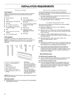
(attached to back of microwave oven) Cardboard template (part of packaging) Aluminum grease filters Charcoal filters (Depending on model, charcoal filters may not be included. See User Instructions.) NOTE: Depending on model, aluminum grease filter and charcoal filter may be combined. Materials - Whirlpool YWMH31017AW | Installation Instructions - Page 3
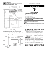
of range/cooktop below. Product Dimensions 17¹⁄₄" (43.8 cm) 16¹⁄₄" (41.3 cm) (401.05³c⁄₄m") 29⁷⁄₈" (76.0 cm) GROUNDING INSTRUCTIONS ■ For all cord connected appliances: The microwave oven must be grounded. In the event of an electrical short circuit, grounding reduces the risk of electric shock - Whirlpool YWMH31017AW | Installation Instructions - Page 4
INSTRUCTIONS Remove Mounting Plate Depending on your model, the mounting plate may be in the foam packaging, or it may be attached to the back of the microwave oven. NOTE: To avoid possible damage to the work surface, cover the work surface. 1. Remove any remaining contents from the microwave - Whirlpool YWMH31017AW | Installation Instructions - Page 5
screws removed in Step 3 cannot be reattached to the microwave oven. 7. Reattach damper plate. Make sure damper plate tabs are inserted into IMPORTANT: If blower motor is not positioned with flat sides facing the back of the microwave oven (as shown), performance will be poor. D A. Damper plate B. Screws - Whirlpool YWMH31017AW | Installation Instructions - Page 6
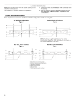
wall studs exist within the cabinet opening, do not install the microwave oven. 1. Using a stud finder, locate the edges of F A. End holes (on mounting plate) B. Cabinet opening vertical centerline C. Wall stud centerlines D. Holes for lag screws E. Support tabs F. Mounting plate center markers 6 - Whirlpool YWMH31017AW | Installation Instructions - Page 7
Mark Rear Wall The microwave oven must be installed on a minimum of 1 wall stud, preferably 2, each other. They must each be 14¹⁄₈" (35.9 cm) from the centerline. 5. With the support tabs facing forward (see illustrations in "Locate Wall Stud(s)" section), align the mounting plate center markers - Whirlpool YWMH31017AW | Installation Instructions - Page 8
well as at both ends. 1. With the support tabs of the mounting plate facing forward, insert to use as guides. ■ If the wall behind the microwave oven (as installed) has a partial wall covering (for example, tile backsplash), be sure the "Rear Wall" arrows align to the thickest part - Whirlpool YWMH31017AW | Installation Instructions - Page 9
oven B. Damper assembly C. Damper blade D. Sheet metal screws 3. Secure damper assembly with 2 sheet metal screws. A B A. Mounting plate B. Support tabs 4. With front of microwave oven still tilted, thread power supply cord through the power supply cord hole in the bottom of the upper cabinet - Whirlpool YWMH31017AW | Installation Instructions - Page 10
has not tripped. Replace the fuse or reset the circuit breaker. If the problem continues, call an electrician. ■ Check that the power supply cord is plugged into a grounded 3 prong outlet. ■ See the User Instructions for troubleshooting information. Installation is now complete. Save Installation - Whirlpool YWMH31017AW | Installation Instructions - Page 11
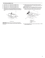
the roof, and rectangular to round transition is used, be sure there is at least 3" (7.6 cm) of clearance between the top of the microwave oven and the transition piece. See "Rectangular to Round Transition" illustration. Rectangular to Round Transition NOTE: The minimum 3" (7.6 cm) clearance must - Whirlpool YWMH31017AW | Installation Instructions - Page 12
to be replaced, call us at our toll free number listed in the User Instructions. Following is a list of available replacement parts. You will need your model number located on the front facing of the microwave oven opening, behind the door. ■ Damper Assembly ■ Mounting Plate ■ Upper Cabinet Template - Whirlpool YWMH31017AW | Installation Instructions - Page 13
danger potentiel et vous disent comment réduire le risque de blessure et ce qui peut se produire en cas de non-respect des instructions. EXIGENCES D'INSTALLATION Outillage et pièces Outillage nécessaire Rassembler les outils et pièces nécessaires avant de commencer l'installation. Lire et suivre - Whirlpool YWMH31017AW | Installation Instructions - Page 14
en bois 2" x 4" (50,8 x 101,6 mm), et parement de plâtre ou panneau de gypse d'épaisseur 3/8" (10 mm) ou plus, dans l'ouverture du placard. ■ Capacité de support de charge de 150 lb (68 kg), ceci incluant le four à micro-ondes et les articles placés à l'intérieur du four à micro-ondes et du - Whirlpool YWMH31017AW | Installation Instructions - Page 15
de courant à proximité du four à micro-ondes. CONSERVEZ CES INSTRUCTIONS INSTRUCTIONS D'INSTALLATION Dépose de la plaque de montage Selon votre modè décharge murale seulement 1. Ôter les vis fixant la plaque de support du clapet anti-reflux à la partie supérieure de l'extérieur du four à micro - Whirlpool YWMH31017AW | Installation Instructions - Page 16
du ventilateur à l'arrière du four à micro-ondes avec les 2 vis ôtées à l'étape 3. 7. Fixer à nouveau la plaque de support du clapet. Vérifier que les onglets de la plaque de support du clapet sont insérés dans les fentes situées sur la partie supérieure du four à micro-ondes. A B A. Orifice de - Whirlpool YWMH31017AW | Installation Instructions - Page 17
(sur la plaque de montage) B. Axe vertical central de l'ouverture dans le placard C. Axes centraux de poteau du colombage D. Trous pour vis d'ancrage E. Pattes de support F. Repères centraux sur la plaque de montage 17 - Whirlpool YWMH31017AW | Installation Instructions - Page 18
inférieur du placard mural. REMARQUES : 5. Une fois les brides de support orientées vers l'avant (voir les illustrations de la section "Identification de la en noir dans les zones grisées. 7. Conserver la plaque de montage à part. ■ Si la rive avant du placard supérieur est plus basse que la rive - Whirlpool YWMH31017AW | Installation Instructions - Page 19
. 7. Serrer solidement toutes les pièces d'ancrage (vis et boulons). Un trou d'angle face à un poteau du colombage mural (Figure 3) 1. Alors que les pattes de support de la plaque de montage sont orientées vers l'avant, insérer une vis à tête ronde de 1/4-20 x 3" dans le trou d'angle coïncidant avec - Whirlpool YWMH31017AW | Installation Instructions - Page 20
qu'il puisse s'ajuster dans le cadre, contre le fond du placard mural. Le gabarit comporte des lignes de découpe qu'on peut utiliser comme guides. ■ Si le mur situé derrière le micro-ondes comporte un revêtement mural partiel (par exemple, un dosseret à carreaux), s'assurer que les flèches - Whirlpool YWMH31017AW | Installation Instructions - Page 21
à micro-ondes. Le non-respect de cette instruction peut causer une blessure au dos ou d'autre four à micro-ondes et le suspendre aux pattes de support situées en bas de la plaque de montage. dégager de la plaque de montage; placer le four à part sur une surface couverte. 8. Desserrer les vis de la - Whirlpool YWMH31017AW | Installation Instructions - Page 22
découpée dans le placard mural E. Patte longue F. Plaque de support du clapet 2. Connecter le conduit d'évacuation au module du clapet antireflux. A B Achever l'installation 1. Installer les filtres. Voir les Instructions d'utilisation pour la mise en place des filtres. AVERTISSEMENT Risque de - Whirlpool YWMH31017AW | Installation Instructions - Page 23
SPÉCIFICATIONS DU CIRCUIT D'ÉVACUATION Cette section présente de l'information de référence uniquement, à l'intention des architectes/concepteurs et constructeurs. REMARQUES : ■ Les matériaux du circuit d'évacuation nécessaires à l'installation ne sont pas fournis avec l'ensemble four à microondes/ - Whirlpool YWMH31017AW | Installation Instructions - Page 24
anti-reflux. ASSISTANCE Appeler le marchand local autorisé ou le centre de service agréé. Lors de l'appel, vous aurez besoin des numéros de mod riel d'installation, contactez-nous au numéro sans frais indiqué dans les Instructions d'utilisation. Vous trouverez ci-après une liste des pièces de
-
 1
1 -
 2
2 -
 3
3 -
 4
4 -
 5
5 -
 6
6 -
 7
7 -
8
-
9
-
10
-
11
-
12
-
13
-
14
-
15
-
16
-
17
-
18
-
19
-
20
-
21
-
22
-
23
-
24
 |
 |
MICROWAVE HOOD COMBINATION
INSTALLATION INSTRUCTIONS
INSTRUCTIONS D’INSTALLATION
DE L’ENSEMBLE FOUR À MICRO-ONDES/HOTTE
MICROWAVE HOOD COMBINATION SAFETY
This product is suitable for use above electric or gas cooking products up to and including 36" (91.4 cm) wide. See “Installation
Requirements” section for further notes.
These installation instructions cover different models. The appearance of your particular model may differ slightly from the illustration in
these installation instructions.
Ce produit est conçu pour l’utilisation au-dessus d’appareils de cuisson électriques ou à gaz de 36" (91,4 cm) de largeur ou moins. Voir
la section “Exigences d’installation” pour d’autres remarques.
Ces instructions d’installation sont valables pour plusieurs modèles. Il se peut que l’apparence de votre propre modèle soit légèrement
différente de celle montrée sur les illustrations dans ce document.
Table of Contents / Table des matières
MICROWAVE HOOD COMBINATION SAFETY
.......................
1
INSTALLATION REQUIREMENTS
............................................
2
Tools and Parts
.......................................................................
2
Remove Cardboard Template
................................................
2
Location Requirements
...........................................................
2
Product Dimensions
................................................................
3
Electrical Requirements
..........................................................
3
INSTALLATION INSTRUCTIONS
..............................................
4
Remove Mounting Plate
..........................................................
4
Rotate Blower Motor
...............................................................
4
Locate Wall Stud(s)
.................................................................
6
Mark Rear Wall
........................................................................
7
Drill Holes in Rear Wall
............................................................
7
Attach Mounting Plate to Wall
................................................
8
Prepare Upper Cabinet
...........................................................
8
Install Damper Assembly
........................................................
9
Install the Microwave Oven
.....................................................
9
Complete Installation
...........................................................
10
VENTING DESIGN SPECIFICATIONS
...................................
11
ASSISTANCE
...........................................................................
12
Replacement Parts
...............................................................
12
Accessories
..........................................................................
12
SÉCURITÉ DE L’ENSEMBLE FOUR À MICRO-ONDES/HOTTE
.........
13
EXIGENCES D'INSTALLATION
.........................................................
13
Outillage et pièces
...........................................................................
13
Dépose du gabarit de carton
..........................................................
14
Exigences d'emplacement
..............................................................
14
Dimensions du produit
....................................................................
14
Spécifications électriques
...............................................................
15
INSTRUCTIONS D'INSTALLATION
..................................................
15
Dépose de la plaque de montage
...................................................
15
Réorientation du moteur du ventilateur
..........................................
15
Identifier la position du/des poteau(x) du colombage mural
..........
17
Tracé sur le mur arrière
...................................................................
18
Perçage de trous dans le mur arrière
..............................................
19
Fixation de la plaque de montage sur le mur
.................................
19
Préparation du placard mural
..........................................................
20
Installation du module du clapet anti-reflux
....................................
20
Installation du four à micro-ondes
..................................................
21
Achever l'installation
........................................................................
22
SPÉCIFICATIONS DU CIRCUIT D'ÉVACUATION
...........................
23
ASSISTANCE
......................................................................................
24
Pièces de rechange
.........................................................................
24
Accessoires
.....................................................................................
24
W10344701B
You can be killed or seriously injured if you don't immediately
You
can be killed or seriously injured if you don't follow
All safety messages will tell you what the potential hazard is, tell you how to reduce the chance of injury, and tell you what can
happen if the instructions are not followed.
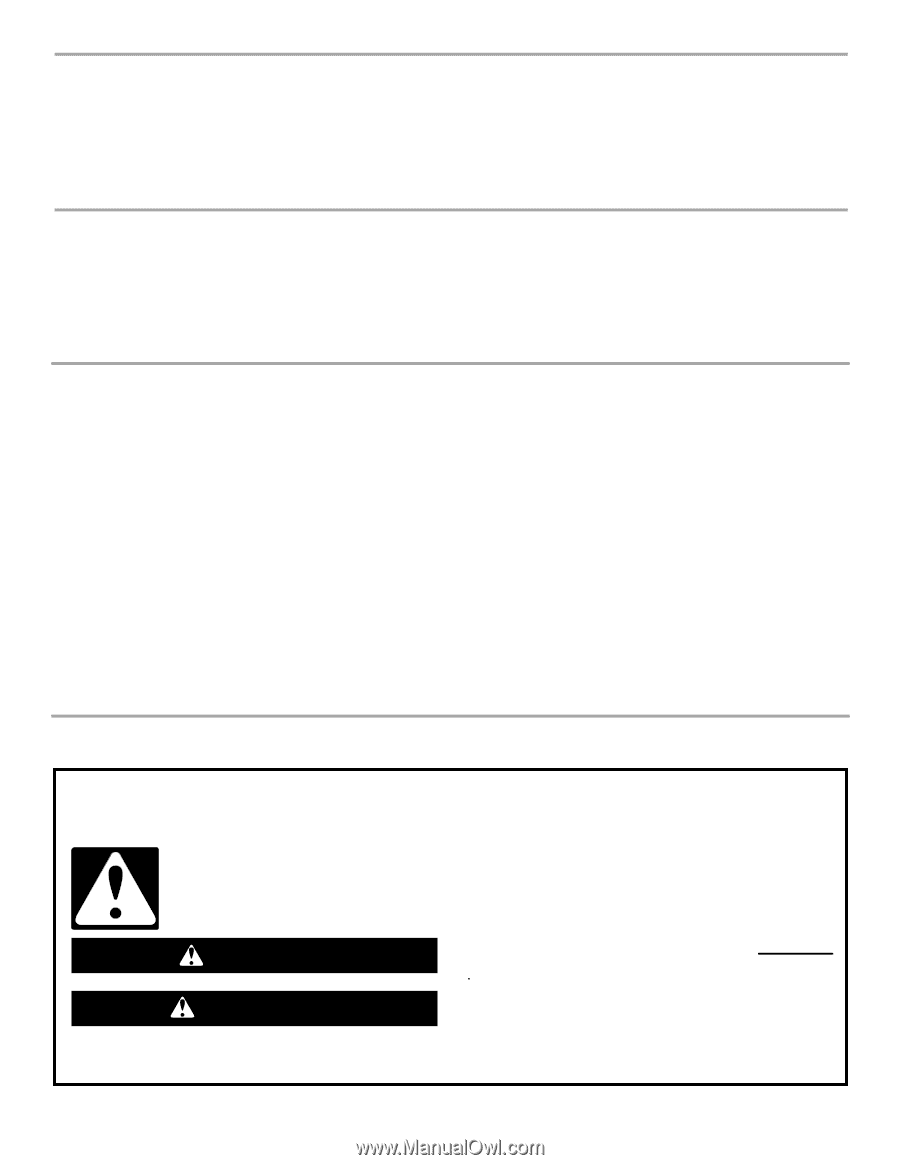
Your safety and the safety of others are very important.
We have provided many important safety messages in this manual and on your appliance. Always read and obey all safety
messages.
This is the safety alert symbol.
This symbol alerts you to potential hazards that can kill or hurt you and others.
All safety messages will follow the safety alert symbol and either the word “DANGER” or “WARNING.”
These words mean:
follow instructions.
instructions.
DANGER
WARNING